Final report for FNC18-1134
Project Information
I am a small-scale farmer, 18 acres, with big ideas. Although the farm has been a somewhat successful truck farm, I am getting too old for the intensive management and I am trying to convert to an organic no-till row cropping system. The experience I have with crimping a cover crop and no tilling into it, has led me to search to find an alternative weed methodology. Flaming, steaming, alternative herbicides have been assessed, but I think the best chance is to develop an in-between row mower: resulting in minimal soil disturbance.
No-till farming has numerous benefits over conventional farming including; improved soil quality, less soil loss, and less fossil fuel. Organic farming has its benefits: no herbicide use, socially desirable and higher price points for products.
Combining those two is a challenge. Organic weed control in row crop situations is cultivation based; in no-till it is herbicide based.
Yet many farmers are trying for this holy grail as can be evidenced from the many SARE grants that focus on no-tilling vegetables into killed cover crop mulches.
Growing row crops in this way is challenging: row crops stay season long in the field, as opposed to vegetables that have a shorter life span.
The cover crop holds the weeds back for a little while but eventually the weeds will come up in between the row. Due to the high residue conventional cultivation is not possible. I want to develop an alternative weed control method: a three-point-hitch mounted, two-row mower that can be used for in-between row weed control. The design will be such that it can be scaled up to a 6-row application.
I want to develop an in-between hydraulically driven two-row mower that is inexpensive and effective, can be easily scaled up to 4 or 6 rows, and be used in row crops like beans and corn.
I want to make the design an open source design: I want to be able to provide design dimensions and drawings to anyone that is interested.
I want to use the mower at my farm.
I want to demonstrate and discuss the mower at my farm, and at field days at MU research center.
Cooperators
- (Researcher)
Research
As described, the goal of my project is to build an in-between row mower to manage weeds that break through the crimped cover crop. Burning is not an option as the crimped weed mat may catch fire. The Rodale Institute has made great strides with the no-till organic row crops approach and has developed a specific crimper roller tool to kill the cover crop (usually rye) before the crop is no tilled into the cover crop.
I can replicate the crimping of the crop by merely driving over it with a two-row no-till planter. But I have not been able to replicate their yield success. I think that the Rodale people have been working the ground a lot longer, and have decreased their weed seed bank so substantially that escaped weeds growing through the mat, in between the row weeds is less of an issue for them than it is for me.
To make the construction of this mower as simple as possible I have gone with the choice for a hydraulic system: a hydraulic pump that runs off the PTO and drives the individual units, basically lawn mowers that run on hydraulic fluid.
I have thought about using a direct mechanical drive off the PTO shaft, but you'd have to come up with a transfer mechanism to drive 3 individual motors. (or 7 on a 6 row mower) and you 'd have to come up with a different mode of turning the mowers.
There is a company that is developing an in-between-row mower unit that uses individual sickle bars of approximately 25 inches wide. But this is beyond my mechanical and engineering abilities.
The process of developing the mower has been relatively straight forward: buy a cultivator and use as many parts as you can; use a solid plate of metal to mount the motor on and use the same plate to be mounted to the individual cultivator.
I built two working mowers that can be used to mow in between rows. I gave a detailed description of the steps and materials needed for constructing one.
I have not used the mower in production yet. This will be spring 2020.
More documentation to follow.
Educational & Outreach Activities
Participation summary:
While working on this project I was contacted by phone a number of times by farmers that had heard about this project through the SARE website, references from Dr. Clark and previous contacts.
The project was described in the Farm Show Magazine, volume 45, edition 5. That did increase the number of calls.
I participated as a speaker on the MU research farm in Novelty, 150 people visited. 28 construction manuals were given out.
I represented the project at the UMC organic field day at Derek Davis', North of Arrow Rock. Approximately 50 participants.
6 local individual farmers stopped at the farm to discuss the mower project.
Learning Outcomes
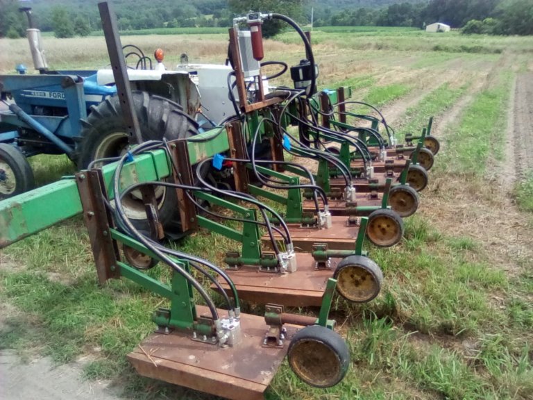
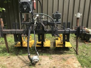
This in-between-row mower is to be used in organic no till where row crops have been no-tilled into a crimped cover crop, or in conventional row crop farming where the in-between-row weed pressure of herbicide tolerant weeds is too great. The initial grant was for a two row mower ( 3 mower units) but this became the prototype for a 6 row mower (7 mower units) that was built in collaboration with Dr. K. Clark with the University of Missouri. Dr. Clark works on alternative weed management strategies in organic row crop production.
The following pictures show the components that are used in the production of the mowers.

In between row mower manufacturing notes:
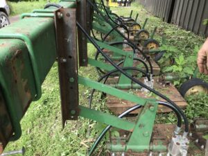
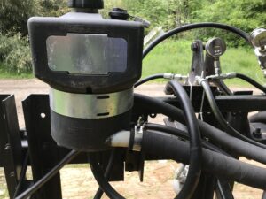
In-between row mower as built: a converted cultivator where the individual gangs have been replaced by individual lawn mowers.
The mowers are hydraulically powered and run off a PTO driven hydraulic pump that drives the individual hydraulic motors.
Total price per unit is approximately $600: $250 per motor, $250 for hoses, and $100 for nuts, bolts, blades, metal and machine shop time.
In addition, the hydraulic infrastructure costs are approximately $2,500. A prototype 2 row mower was built and a 6 row to test for field application.
With the design below a 6 row mower can be built. (After field testing it appears that the components and layout will allow the addition of two hydraulic motors to an 8 row mower without additional engineering)
Mower description:
When the prototype in-between row mower for 2 rows was built the start was a second hand four row cultivator, purchased for $300, brand or make are to this day unknown. For the 6 row mower a second hand John Deere 8 row cultivator was purchased.
The design and components of these cultivators are the same, but the parts are not interchangeable between cultivators. For example: the mechanism used to attach a cultivator unit to the toolbar is the same but the dimensions of the bracket are different for a 6 by 8 steel tube as opposed to a 5 by 6 steel tube. The dimensions of the parallelogram differ, etc. Both mowers, however, could be replicated exactly. This unit can be reproduced with all the individual components. However, cost wise and labor wise, there is a definite advantage to going with whatever is available and modifying as you see fit.
One design decision to make is at which maximum height the unit will be operated .
Since the mower won't be mounted on a front end loader (too heavy) and it becomes rather expensive to purchase a high boy it will go on the three point hitch. The higher the tractor clearance, the closer to canopy time you can mow. As the shanks are approximately 16 inches tall, and they are replaced by a 4 inch tall mower deck the parallelogram used in the cultivators will have to be lowered and an extension has to be made. The extension is made from two pieces of 3/8th inch thick 3 by 3 inch angle iron of 2 foot. It is mounted on the toolbar with the U-bolts that were salvaged from the cultivator. In the process of revamping the cultivator only stock material was used: flat steel, angle iron and standard bolts and nuts.
The second decision is the width of the mower.
In this day and age of in field GPS and computer adjusted three point hitch assemblies 1 inch minus could be possible, but given the small budget for this project that was never an option to pursue. 30 inch rows, minus 1.5 inch for the row leaves 28.5 inch of mowable width. In order to keep options open width was set at a box of 22 inch wide, with a mower blade of 21 inch. The box is made of 3 parts and the side can be moved out up to a width of 26.5 inches. Mower blades from 21 to 26 inch can then be used. With 28.5 - 22 = 6.5 inc, thus 3 and a quarter inch on either side of the crop row. This width decision is one to be made depending on trust in your steady hand, your side slope and experience. 24 inch seems doable.
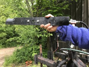
What is not readily available is the actual mower box and this has to be fabricated.
The top plate of the mower box has to be strong: it has to be able to hold the motor, the rear wheel and the attachment to the frame. 3/16th thickness sheet will suffice. The width of the top plate was designed at a width of 18 inches to optimize material that is cut from a 48 by 96 sheet of metal. Given that the metal cost is only a fraction of the total cost the width of the plate will be 22 inch. Length of 32 inches is good The motor is placed in the middle of the width of the top plate, and is placed 17 inches from the front of the plate to reduce the throw out of material toward the tractor. (During field testing no discernible throw out to the front or back was observed).
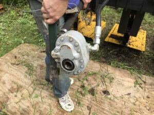
The hydraulic motors have standard configurations: 3 1/4 inch diameter hole with two slots to bolt the motor down. A standard 3 1/4th hole saw at ACE hardware, (they are also available on-line) cuts this hole. As the plate is 3/8 inch thick a drill press was used. The plate is also rather wide, so you will need a drill press that has at least a 14 inch arm to get to the middle of the plate. If none is available a magnetic-drill may have to be used. Each hole took about 5 minutes to carve out. Depending on the cultivator assembly you will have to drill a number of holes in the plate. 1/2 inch bolts were used to attach the toolbar to the plate.
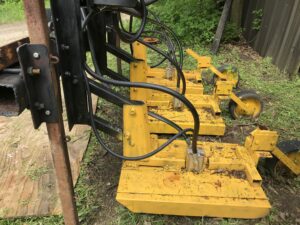
The sides of the mower decks were made out of 1/16th thick metal. Strips of 32 by 9 1/4 inch were made and bent to a 90 degree angle into 3 and 1/4 inch vertical, 6 inch horizontal. When the side plates are moved out to 26 inch this leaves 4 inch of overlap on the top. The front corners were bent over double to be stronger.
An improvement would be to make the sides stronger, but 1/16th was about the maximum thickness the brake could bend, otherwise you will have to weld two plates together. In-field the sides did hold up. If you know the width of the box that you are going to use you can weld two strips of 3/16th to the sides, or you could use 3.5 by 3.5 inch angle iron.
BLADE/ MOWER
One of the first things to be decided was the mower blade width. How close can a farmer cultivate? How close can a farmer mow? Cultivation is more forgiving than mowing. A shank or shovel can be 4 inches away from a plant, but still provide excellent weed control as the soil is thrown up towards the base of the plant.
As we are not sure of what is practically possible we have opted for a conservative 22 inch blade. This does leave about 3 inches on either side of the stems of the plants, as these do have a nominal thickness and are not perfectly straight once germinated. (It is understood that once we show the validity of mower weed control this system can be updated with automated GPS and you may get within an inch of the crop). Mower blades come in a variety of shapes, quality and thickness but are readily available. The idea is to make this mower with off the shelf parts, but right off the bat: you have a hydraulic motor on which you want to attach a lawn mower blade., the part is simple, but probably beyond the precision ability of a farmer. In order to be able to adjust the width of the mower blade (by buying different sized ones), you have to be able to adjust the width of the mower box. The front end of the box is open to prevent the weeds from being bent down below the mower blade. The back is open so that residue can leave the mower without clogging up.
The mower box is made out of three different pieces. A flat 3/8th sheet of steel on which the hydraulic motor is bolted is the base of the mower. It is thick enough not to bend and is used to mount the individual mower to the toolbar gang. On the sides there are two pieces bolted -- bolted pieces are flat pieces that were bent with a brake. To be able to bend the metal it had a maximum thickness of 1/16th In hindsight, either the 90 degree angle has to be welded with thicker metal, or this part has to be made in a different way or outsourced
The wheel and a mounting mechanism was salvaged from the cultivator gang and was reused and attached to the back of the mower top. As the motor has to be in the center and the best position for the carry wheel is in the center as well (although it doesn't have to be) the mounting brackets had to be offset on the plate. Two wheels were salvaged and mounted on 2 by 2 inch square tubes which were mounted on the toolbar for depth control.
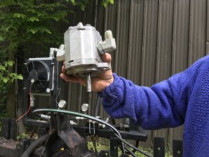
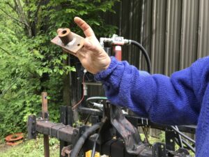
The mower blades are standard, pick the heaviest ones. A local black smith fabricated adapters to mount the blade to the hydraulic motor. A 1 1/2 inch tall hollow cylinder that fits snugly around the shaft of the hydraulic motor is welded onto a 1.5 by 3 inch metal plate. In the center of the plate a small hole is drilled so that the adapter can be bolted onto the shaft (when specifying the hydraulic motor make sure the shaft has a threaded hole) Then two more holes are drilled through the mower blade and the small metal plate. Small regular 3/8't bolts are used to bolt the blade to the adapter. The mower blade should be approximately 3 inch below the bottom of the deck plate.
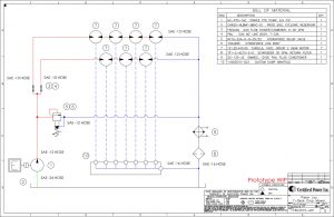
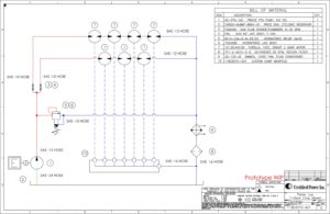
Now the units have to be powered. For this project an engineering firm was engaged for calculations. The description below goes through the components as the oil would go through the system, starting at the pump. The engineering firm suggested the following setup:
- a PRICE hydraulic PTO pump, off the shelf, that puts out 22.5 gallon with a maximum pressure of 3000 psi at 540 rpm., it goes through a high pressure hydraulic line to a pressure gauge which is installed in the line that goes to a safety valve (mounted on an inline T). This is the motor for a 6 row mower, for the 2 row mower a PRICE hydraulic pump with an output of 11 gallon was used.
- hydraulic lines
SAE 10: 5/8th inch
SAE 12; 3/4 inch both up to 3000 psi. From the flow divider in the center it takes approximately 12 ft to the outer motor and 10 ft. to go from motor to motor. Each motor will have 1 line coming in, and 2 going out, one to the next motor and the small one from the motor case to the manifold.
SAE 16: 1 inch, low pressure from the collection point of both return motor lines and the pressure overflow lines, all return flows to the radiator,
SAE 24: 1 1/2 inch, low pressure from the cyclone to the intake of the PTO. See flow diagram. All fittings and couplings used are JIC fittings. The pressure gauge is the only part of the system that is pipe thread and not JIC hydraulic fitting:it needs teflon tape to prevent leakage. There are a number of T fittings and couplings and reducers, all can be found either on-line or at specialized hydraulic stores. Your local carquest only can do so much. There are a few O ring connections: from and to the PTO motor, into the radiator and into the manifold.
-from the pump the fluid goes through a safety valve. This consists of two parts: the physical housing and a spring loaded relief valve. If there would be an issue with the motors, or the PTO driven pump puts out too much pressure the valve will open and bypass the motor circuit.
There are two ways to plumb the individual motors: in series or parallel. In series all the fluid goes through all the motors. In parallel, the flow is divided in equal parts and each motor gets (supposedly) the same portion of the total flow. As the flow dividers are rather expensive and can cause inaccurate distribution the mowers were placed in series. Hydraulically speaking there is a limit on the number of motors you can run with one PTO pump before the pressure goes up dramatically to still power the last motor.
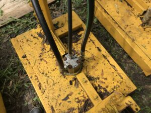
Thus from the safety valve the flow goes through a flow divider, it consists of two parts, a physical housing and an engineered part that divides.
From the flow divider the flow goes into motor 1, through motor one, out of motor 1 and to motor 2, and 3 and 4. The other flow from the flow divider side goes through motor 5, 6, and 7. All motors are the same: they have three ports: one for flow in, one for flow out, and a case drain which can relieve pressure spikes and protect the motors from seal blow out. The small case drain lines from all 7 mowers come directly together in a custom made manifold. The manifold has the dimensions of a brick, it has 7 inlets where the small lines come together, and one larger outlet where the combined flow goes out to the reservoir. A simpler alternative is to use 7 "T" couplings to connect all the lines, but each "T" will have to have a connector to the next one, making this more costly. The flow from the manifold or "T" goes into the bottom of the cyclone.
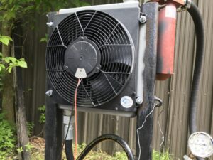
The flows coming from 1,2,3,4 and from 5,6,7 are then combined through a T connection and continue as one flow through a cooling unit, like a radiator for hydraulic fluid. It has a 12 volt fan attached that can be direct wired to the tractor battery. On top of the outgoing line from the radiator a hydraulic filter is mounted.
From the filter a hydraulic line goes to the cyclone. This "cyclone" is a relatively new component in hydraulic engineering. Its function is two fold: it has a small reservoir of approximately 2 gallons of hydraulic fluid and it removes air bubbles that have been generated by the normal flow through the system. This cyclone replaces the need for a large hydraulic tank and reduces the total amount of hydraulic fluid needed. (A rule of thumb engineering standard for the volume of a conventional tank is the amount of fluid that the PTO pump puts out in 1 minute. (22 gallon in this case). Either a cyclone or a reservoir will work.
The cyclone has three openings: 1 for fluid coming from the main hydraulic lines that drive the motor, a smaller one that takes in the fluid from the manifold where the seven case drain lines come together from the individual motors and one outlet that goes back to the PTO pump.
Bill of material:
PTO pump: hc -pto-1a, Prince Pto pump, 9.9 cid (cubic inch displacement0, 22.5 gallon per minute.
Website below is just one of many that sells these pumps.
PRICE Cyclonic reservoir, : CHR20-NLBMF-BBVC-01 This is a relatively new product. The website: https://cyclonehydraulics.com/ You may have to go through the distributors.
FLow divider: two parts
FSEAXAN SUN FLOW DIVIDER/COMBINER 6-30 gpm. This is basically the housing part of the flow divider.
PML sun 90 degree, line body T-33a. This is a part that is screwed into the housing, that divides the flow
Relief valve:two parts
Housing: 702280 Hydra force line body
Relief valveRV10-22a-)-N-25/22
The motors:
121.20.443.00 Turollo ,19 cc/rev, group 2 gear motor (Italian made). Equivalent motors with the same specs may be found. Be sure to get the counter clockwise motors. These motors are generally NOT bi directional, meaning that it does matter which way the flow goes through the motor. The direction of the rotation is determined looking from the shaft up to the motor! This means you need a counter clockwise motor if you want the blade to spin like on any lawnmower. On this mower a straight shaft with key was used. Other shafts may be suitable too.
Radiator:
EMMEGI, 12v cd fan, fluid conditioner, S2-125-JE
Filter:
a 30 gpm Schroeder return filter was used: tf1-2-AZ10-S-D The filter can be mounted directly to the radiator with the correct hydraulic fittings.
https://schroederindustries.com/Pages/Home.aspx
Starting the mower
When first starting the mower it is important to fill up the cyclone reservoir between the minimum and maximum fluid line and to engage the PTO as slowly as possible. This can be done by turning the pump by hand, until all mowers slowly turn, and then engage the PTO and let it run as slow as possible. Motors can blow up from air hammer and shocks if the PTO is running directly at operating speed. Slow and gentle is key when just starting it up.
Project Outcomes
Although my design is specific to the toolbars I started with, the information in the description is sufficiently detailed that it can be used by other farmers. After construction the mowers were field tested in conventional soybeans and sunflowers (30" rows). The mower does work well, but has not been applied yet in the situation that I envisioned it for: in no-tilled beans in crimped rye. The mower was tried in conventional soybeans and sunflowers (Due to changes in personal situation there was no farming activity last year)
During the planning and construction process there were two farmers whom I interacted with frequently. One farms on the silt bluff/ hills in north east Missouri, and had suggestions on decreasing the sway in the mower and is wanting to build his own mower.
The second farmer will be using the 6 row mower this year. I intend to document this on Youtube.
A major improvement would be the use of small rotary cutter blade to provide better protection to the blades when they hit obstructions. Currently the blades (and mower motors) are protected by a shear pin/ key way between the hydraulic motor shaft and the blades. This is not an issue at Wilfarm but it could be on rocky ground or very uneven ground.
An alternative to protect the motor is to have a standard rubber connection between the motor and the upper part of the shaft but that entails extra parts and complicates construction.