Final Report for FNE12-769
Project Information
Oyster aquaculture is rapidly expanding into subtidal waters, which requires different culture techniques and is subject to different regulations than typical intertidal shellfish culture. Due to the increased water depth and location further offshore, new methods to access the shellfish as well as protect and increase feed to oyster seed must be designed. This project investigated a new airlift system to make accessing shellfish easier than SCUBA or using mechanical means, as well as designing and implementing an upweller system which is located on the bottom of the ocean to fit within current subtidal aquaculture guidelines. The airlift system resulted in a time savings of 75% over the typical SCUBA culturing method (an average of 7 minutes for the airlift system versus 30 minutes when using SCUBA), though there is room for optimization to lower costs and increase efficiency. The initial costs per cage were approximately $160, not including 1 SCUBA tank to raise 3 cages at a fill cost of $4-8. The upweller functioned exactly as designed, through did not result in an increase in growth due to undersized pumps and limited battery power. The upweller only cost approximately $150 to build, however the largest commercially available batteries were purchased to power the system and combined with cables, they cost over $1400. If continuous power can be implemented, larger pumps can be incorporated, and increases in growth and survival will result in productivity gains for subtidal aquaculturists. The two novel culturing methods designed through this project must still be optimized to fully benefit subtidal oyster farmers, but represent the first step towards a large increase in safety and cost savings for farmers throughout New England.
Introduction:
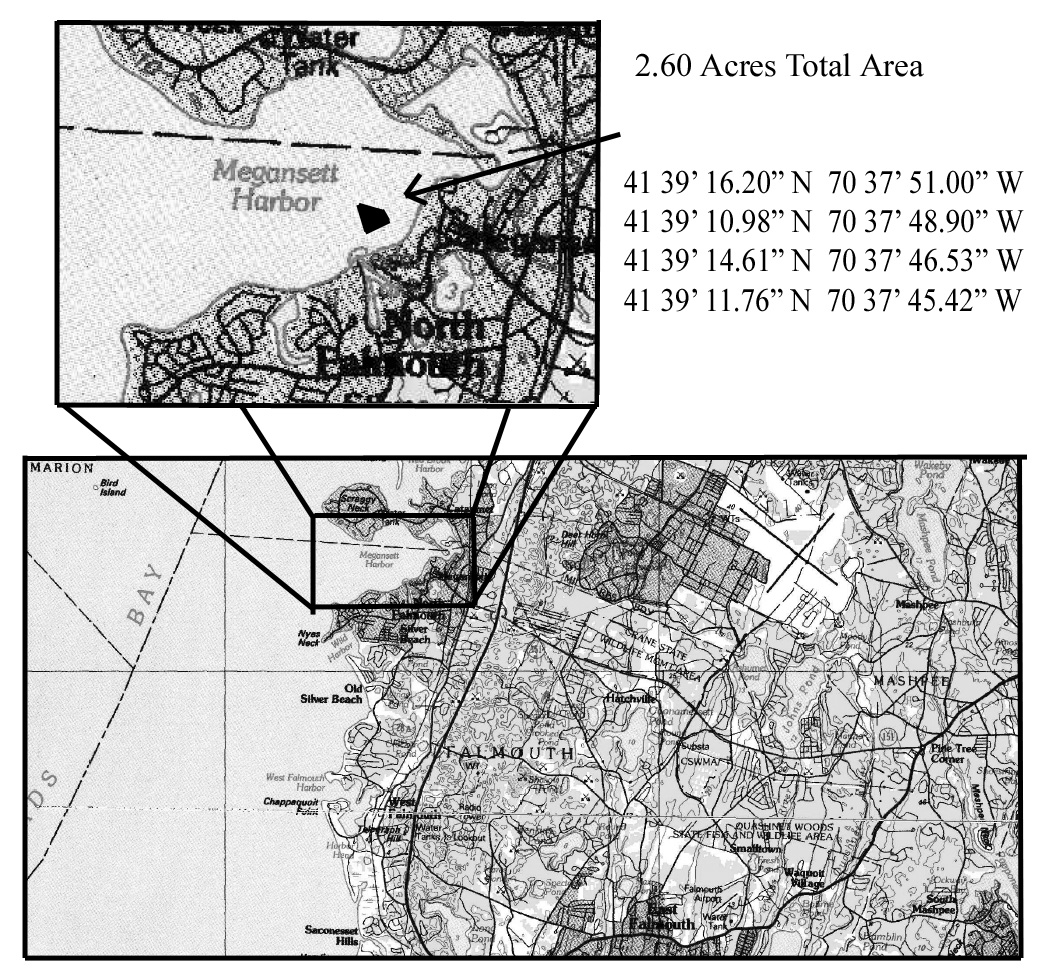
Ward Aquafarms, where the project took place, is located in North Falmouth in an area known as Megansett Harbor (Fig. 1). The site is 2.60 acres, and is permitted to grow both Eastern oysters (Crassostrea virginica) and quahogs (Mercenaria mercenaria). There is a mooring field lining the southern edge of the lease site, and the channel entering Rand’s Canal lines the western edge of the site. The eastern and northern edge is open to the rest of Megansett Harbor. The benthic habitat within the confines of the 2.60 acre site is comprised of essentially barren flat sand, with occasional seaweed and common slipper snails (Crepidula) attached to small rocks throughout. The operation is currently a family business, and is operated solely by the husband and wife team of Dan and Jen Ward. The farm currently comprises 75 cages containing 1000 bags which hold as much as 1,000,000 oyster seed. The permitting process for the farm was started in February of 2010, and the farm has been operational since the summer of 2011. In 2012 we secured a mooring and currently have an 8’x20’ floating dock at the site to work on. All oyster operations are conducted via SCUBA, then the oysters are brought to the dock to be sorted, cleaned, etc.
This project was completed entirely by owner/operator Dan Ward with assistance with 1 seasonal employee from May through September. Diane Murphy of Cape Cod Cooperative Extension and Woods Hole Sea Grant served as technical advisor for this project and assisted with technical questions on implementation and data analysis.
- 1. Investigate a novel technique to bring cages to the surface by developing an airlift system to lift the cages instead of using SCUBA or a hauler to drag them out of the water. 2. Design and implement a system that will be on the bottom of the ocean to fit within current subtidal shellfish aquaculture guidelines, which will utilize the same principle as a common shellfish upweller to protect juvenile shellfish while increasing food availability.
Cooperators
Research
Air-assisted cage lift system
Summary
By bringing compressed air to the site (in a SCUBA tank or similar apparatus), farmers can attach an airline hose to the tank and begin filling PVC tubes surrounding the cage. As the PVC tubes inflate, the cage will rise to the surface. Since the cage is attached to an anchor on one side, and to the next cage in the line on the other, it also will not move laterally while on top of the water, which means the cage will sink back to approximately the same footprint once tending the shellfish is complete. Once the farmer is done tending to the oysters, he simply opens the valve at the surface and water pressure will push the air out of the PVC, allowing the cage to return to the bottom.
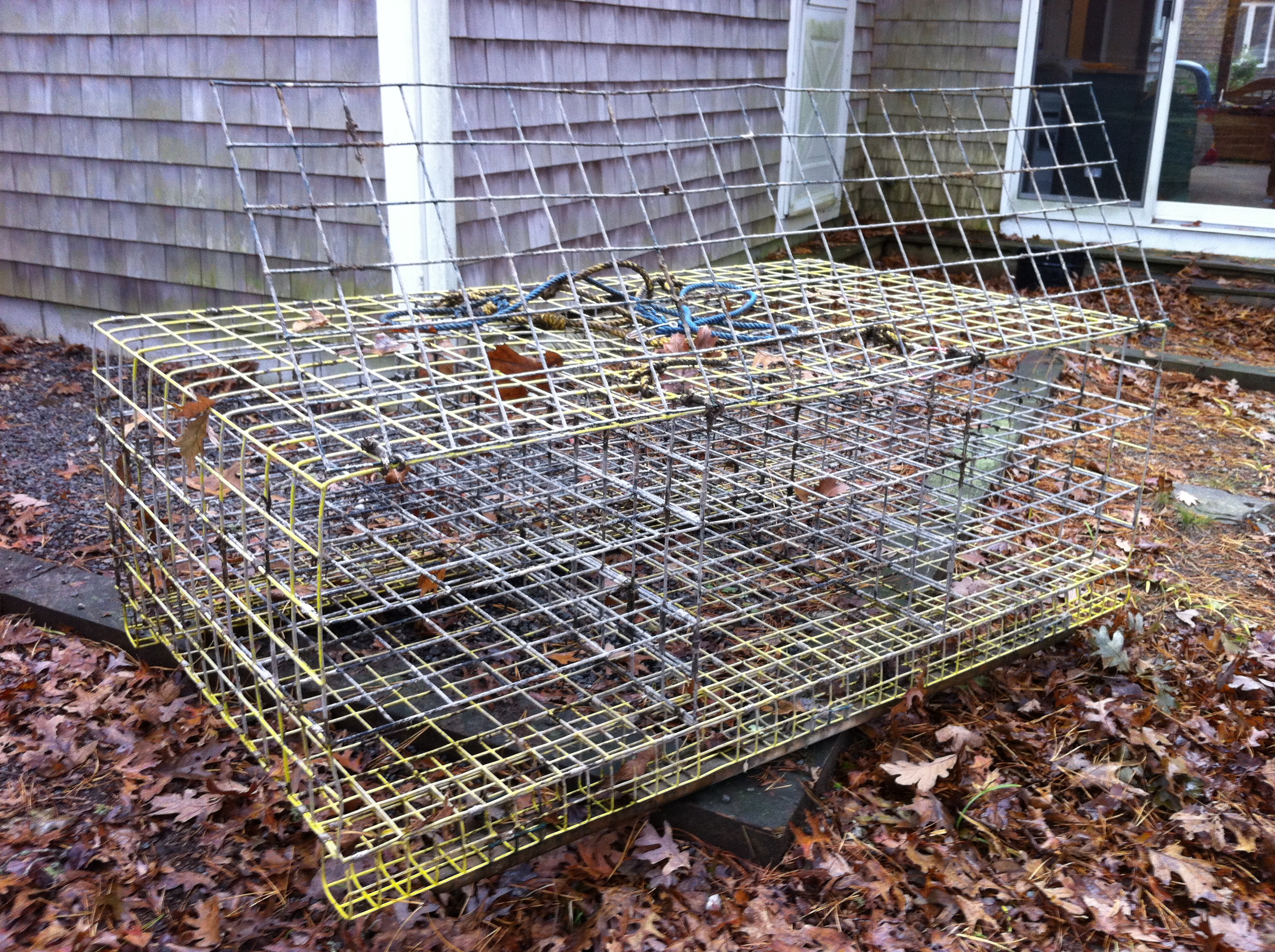
Typical oyster culture in subtidal waters is performed in cages that are constructed of coated wire, similar to lobster cages, utilizing 3” mesh, weighing approximately 75lbs (Fig. 2).
The air-lift system which was designed started with the same cages, and then modifications were made to allow the cage to be lifted using air instead of the typical hauler system (Fig 3).
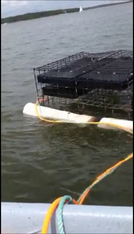
The proposed design included four, 4” schedule 40 PVC tubes attached on the four sides, open at each end, with a rubber bladder inside the PVC. The tubes were designed to be the same length of the cage (two, 36” tubes, two, 63” tubes) to lift the cage out of the water. The cage also was proposed to have four, 2” air filled balls attached to the upper corners to keep the cage from tipping over while being raised, a weight to prevent lateral movement on the surface and an air line running from the surface down to the cage from which to put air into the system. While some of the proposed elements were implemented as proposed, several other proposed modifications had to be changed as the project went forward. Initially, the four, 4” schedule 40 PVC tubes were attached to the cage, however the cage would not raise to the surface fully (Fig. 4).
The initial 4” float design did not work for two reasons: 1) four 4” floats did not supply enough lift to bring the cages to the surface, and 2) with four air entry points and four air exit points, only one side of the cage would lift at once (Fig. 4). This brought about many iterations of possible solutions to the problems. The first problem of not enough lift was simply fixed by changing out the 4” PVC for 6” PVC. Two 5’ sections and two 3’ sections of 4” PVC provide 2,411.5in3 of displacement which equals 11.16 gallons of seawater, which was very close but not enough lift with oysters and bags in the cage. While only two 5’ sections of 6” PVC provides 3,391.2in3 of displacement which equals 15.70 gallons of seawater, which is more than enough lift to bring the cage to the surface.
The switch in PVC sizes solved the problem of not enough lift, however the more complicated issue was that of getting the cage to rise to the surface evenly and stay on the surface. The initial proposal called for an internal rubber bladder that could be inflated and deflated as needed. The two commercially available options for a rubber bladder is a simple inner tube or a reinforced PVC-coated pad which can be inflated from the surface. The rubber bladder is cost effective ($80 each), however much too brittle to be used in a marine environment. The reinforced material would work excellent as a lifting device, however at approximately $320 in costs for just that part of the system per cage; it is a prohibitively expensive option. The next best option was to use commonly available, relatively cheap PVC tubes. PVC is a robust material, will have a long life in a marine environment, and is available for cheap pretty much anywhere.
Initially two 5’, 6”-PVC sections were attached to either side of a cage with 12-gauge aluminum wire in four spots per PVC tube. Compressed air tubing (3/8”) was attached to a SCUBA tank at one end and brought to a four-way manifold located centrally under the cage. From there ¼” compressed air tubing was distributed to four ¼” barbs located on each end of the tubes, which were tapped and installed into the 6” PVC section. While this mechanism worked to get air into the system, the air would only move to the side that was higher in the water column, and then rush out into the water; therefore only one corner would lift at once. Four valves were then installed onto the manifold (substantially increasing costs at approximately $8 each), and each was only opened ¼ in order to create back pressure on the airline, and cause air to be pushed equally to each air inlet. This worked well to cause both airtubes to lift at once, however the air still went to only one end. The next modification was to cut and cap each 5’ section into two, 2 ½’ sections, each with one air inlet and two ¼” air outlet holes located centrally on each tube. This design allowed each inlet to get air equally, which caused the cage to rise to the surface equally and right itself once at the surface. The valves on the manifold were removed in the final design before implementation by reducing the airline going to each outlet to 1/8”. This allowed the back pressure on the airline to be achieved through smaller diameter aquarium tubing, reducing costs and simplifying the design. Cheaper manifolds were purchased as well with six ports, in order to be able to attach multiple cages in series (Fig 5).
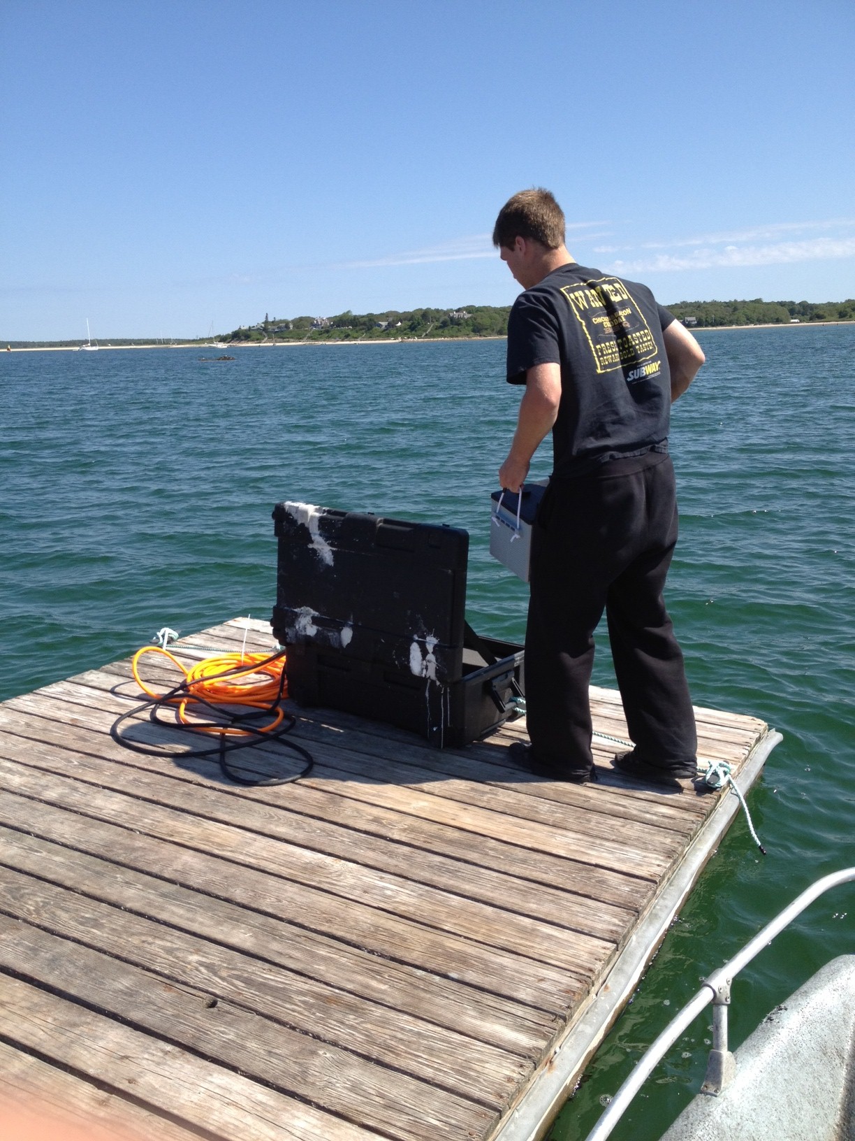
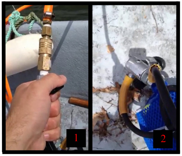
In order to lift the cages, a typical SCUBA first-stage regulator was modified to be able to release air from the tank into a 3/8” compressed air line (Fig. 6). This would allow the 3000psi tank pressure to be lowered to a consistent 150psi which would go to the cages. The air would be slowly turned on with a ball valve, and then the cages would begin to rise to the surface (Fig. 7). Once all of the cages were at the surface and stable, the ball valve on the air line would be closed, sealing the PVC tubes from letting any water back in. The cages would then stay floating at the surface to allow the oysters to be cleaned, graded, etc. Once the work is finished, the air line is disconnected from the SCUBA tank, released back into the water on the buoy to which it is attached, and the air begins to leave the system back through the airline from which it came. The cages sink back to the ocean floor in the same spot where they came up due to anchoring on both sides, and the airline is easy to find next time by just picking up the buoy it is attached to on the surface.
Underwater upweller
Summary
Current subtidal shellfish aquaculture regulations limit structures in the water column to no higher than 18” off the ocean floor. This prevents subtidal farmers from taking advantage of current upweller systems that protect oyster seed and pass large amounts of food by the shellfish to increase their growth rate. A system was designed to mimic the same principles of protection and increased food in typical upwellers, however move the system to the bottom of the ocean below 18” to fit within current regulations. Through a battery powered system located on the ocean floor, subtidal farmers can buy smaller seed and take advantage of the gains in growth and survival without needing the upweller to be located on the surface.
The proposed upweller system consisted of the same wire-coated mesh oyster cage (Fig. 2), and utilized the same method of air-lift to the surface as the air-assisted cage lift system (Fig. 7). The cage was to be surrounded by fiberglass matrix, and epoxy coated to create a hard exterior to the cage, then a window was to be cut and fine metal mesh (2-4mm) was to be inserted. On the opposite end, two small waterproof submersible pumps were to be attached to pump water through the structure, and located in the back of the underwater upweller were to be two waterproof sealed 12V DC batteries with wet-connect power cables to power the submersible pumps.
As work into the airlift system progressed, it became evident that the lift needed to bring a system such as the underwater upweller to the surface would be prohibitively large. Also, by only having one window to pull water through, if there was ever a pump failure then water flow would be so low that high mortalities would be almost guaranteed if the pump was not repaired immediately. Therefore, to make the system more robust the design was modified, while keeping the same basic elements intact and bringing about the same result.
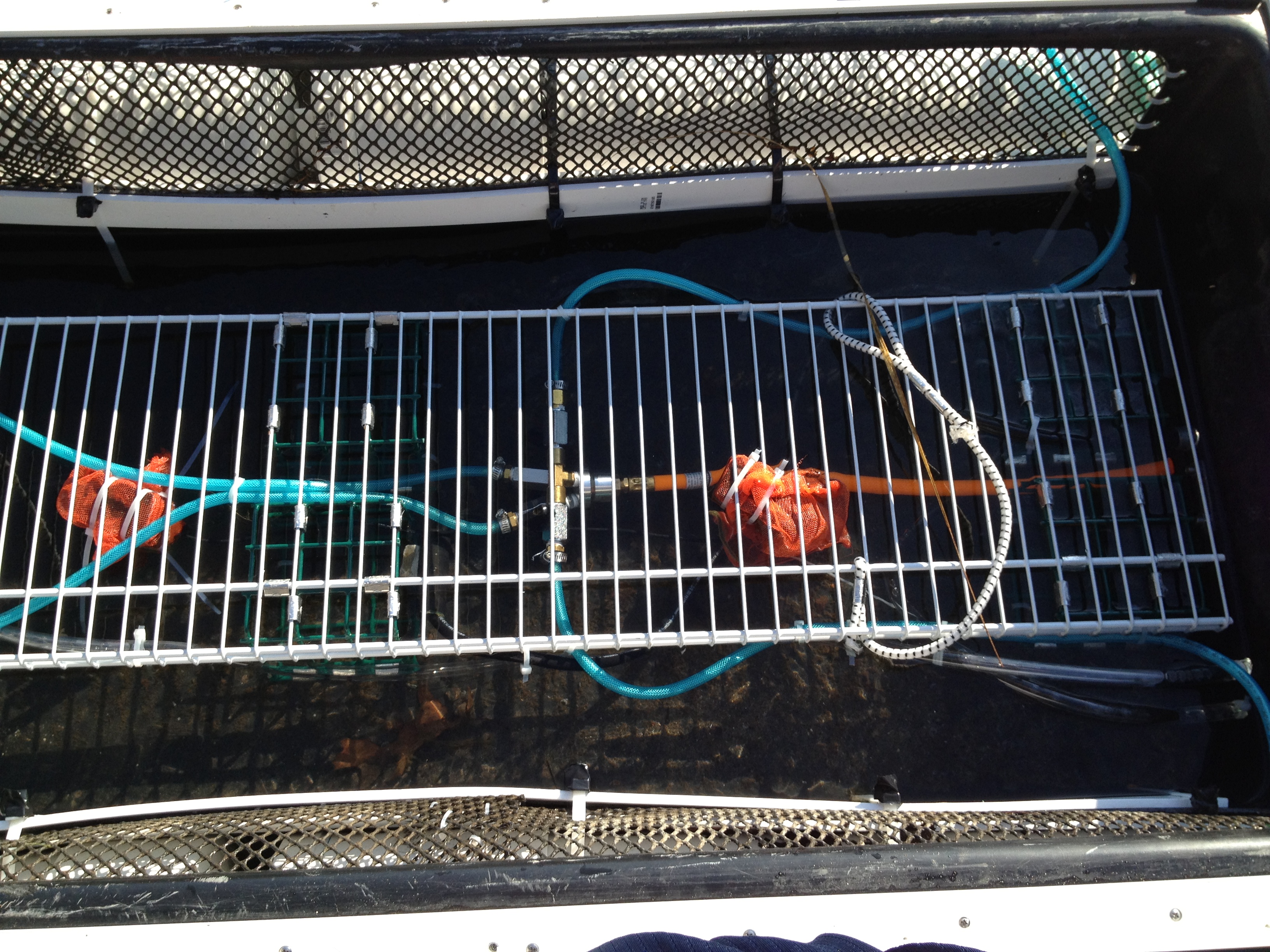
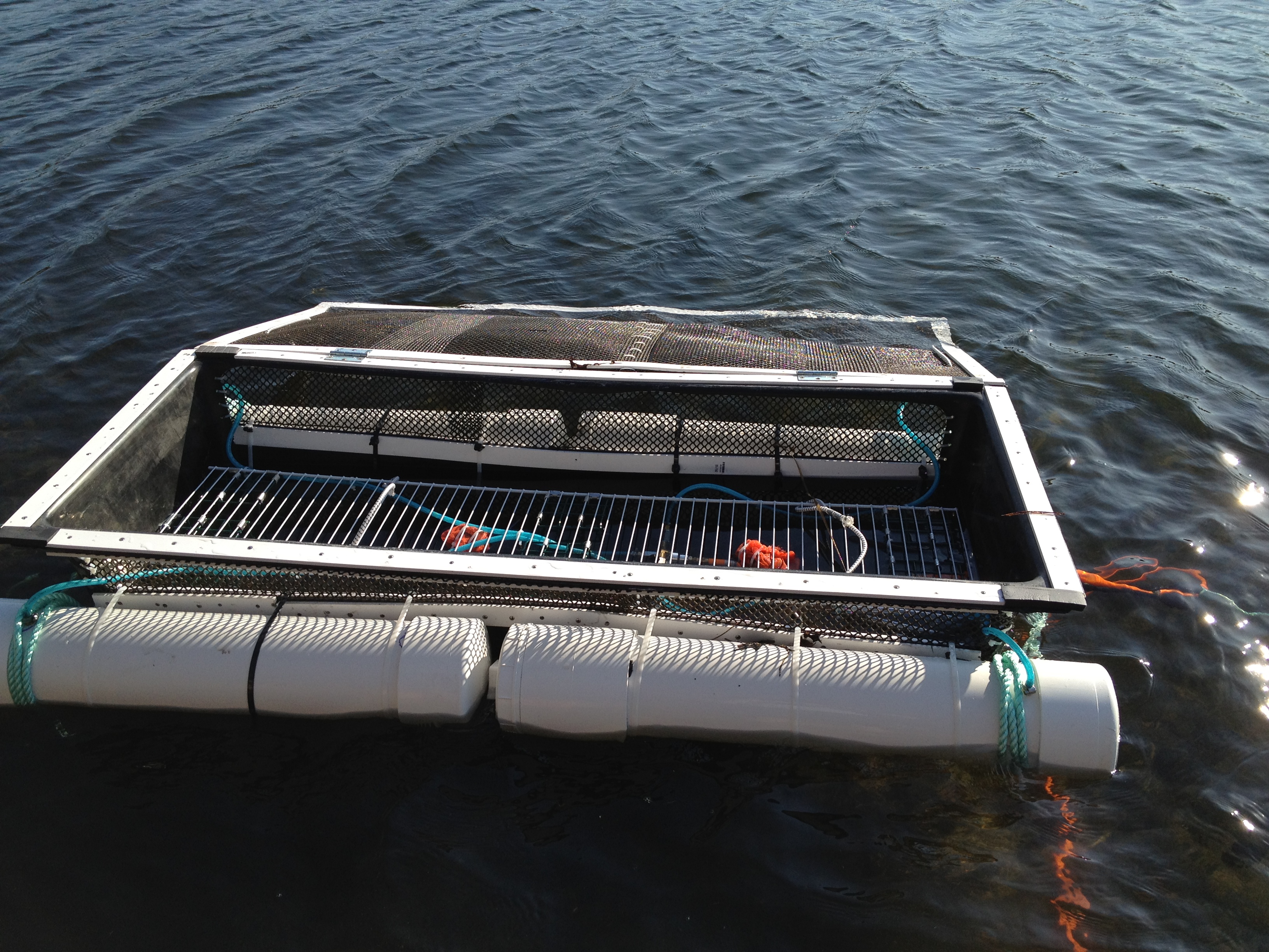
Instead of the large wire-mesh cage to hold the oyster spat bags, a 6’x2’ fiberglass tank was purchased, and large 6” windows were cut along the entire length on both sides. The windows were fitted with 9mm APDI mesh and connected to the tank with 2” strapping to seal the edges (Fig. 8). A vinyl-coated rack was attached to the tank in order to keep the bags centrally located in the water column within the cage. This way water would be able to flow freely around the upweller instead of only from the top down. A lid was then constructed and installed on top of the upweller in order to keep any predators from entering the upweller. The lid was put on hinges and constructed out of the same 9mm ADPI materials and 2” strapping. The lid was then held down on either end of the upweller with shock cord and S clips.
Installed within the underwater upweller were two submersible pumps, individually connected to battery power, so that each could function independently of the other in case of failure. Each pump was wrapped in 1.5mm nylon mesh to act as a crude filter to remove large particles in the water column before they clogged the pump. This filter was cleaned every two days when the bags within the upweller were cleaned. Each pump had a 3/8” plastic hose leading from the pump to a hole drilled in the exterior of the fiberglass tank by which water was removed from the system. The removal of water from the system would cause more water to enter through either the top lid or the windows on the side. The pumps were strategically located below the oyster bags, this way when water was pumped out of the system, the new water would be forced to travel through the oyster bags before getting to the pumps, thereby increasing food passing by the oysters.
The proposed design was to connect each pump to a 12V DC battery located at either end of the upweller system. Once the airlift system was investigated further, it was clear that it made no sense to include the batteries into the system which had to be lifted up and down. Incorporating the batteries within the system would only require more lift to raise the cage up and down, whereas if the batteries were separated from the system, less water would be required to be displaced in order to raise the upweller. Therefore the batteries were moved from inside the upweller to a watertight box on the surface with sufficient floatation to hold the batteries and float above the upweller (Fig. 9). The proposed design was to have two 1.25amp pumps and one standard car battery that could be swapped out and recharged; however as the plan progressed those expectations had to be modified. A standard car battery is 45 amp/hours (a/h), and in order to maintain integrity should only be drained 50% before recharging. Therefore if two 1.25amp pumps were running off of it, the battery would need to be switched out every 9 hours.
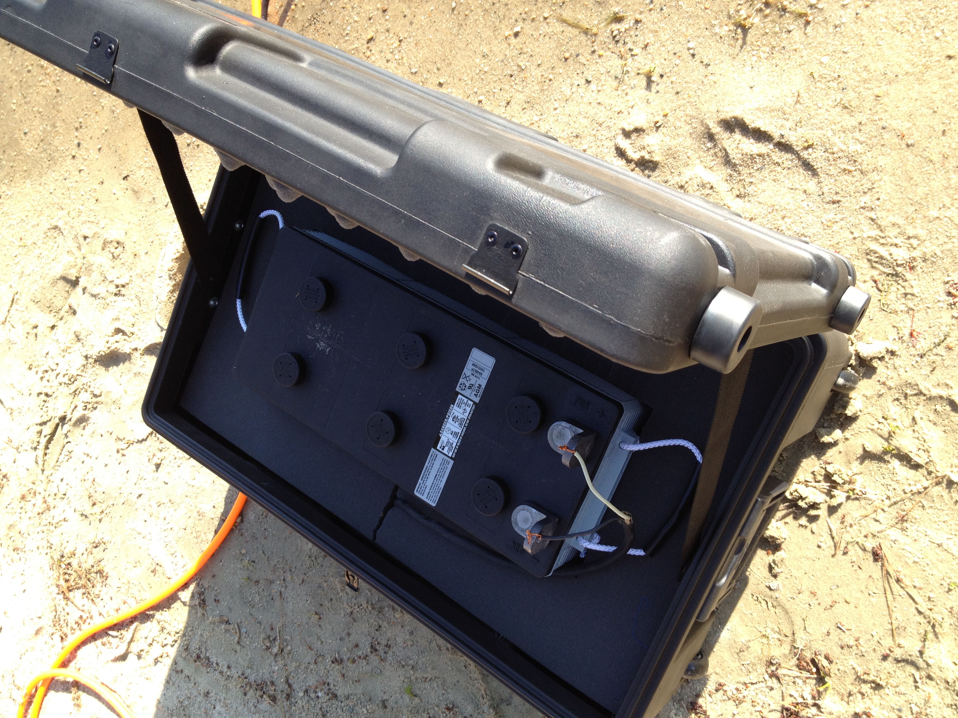
Clearly either the pumps had to be downsized, the batteries needed to be bigger, there needed to be a way to recharge the batteries or some combination of all three. In order to purchase solar panels that would have any meaningful impact on battery life, the cost would be many thousands of dollars, and while possibly a long-term solution, definitely outside the scope of this project. The first option was to get bigger batteries. The biggest batteries commercially available are for solar installations and have a maximum capacity of 225a/h. Unfortunately they are $550 each and 120lbs, which brings other complications and unexpected costs (Fig. 9). Even with the increased battery size, the two 1.25amp pumps still would only function for 45 hours before needing to be switched out. If there was any kind of weather event or mechanical breakdown which prevented accessing the site, all of the oysters could be lost with very little room for mistakes. Therefore the pumps had to be downsized as well. The pumps that were eventually purchased are 0.5amps, which meant that the battery still needed to be switched out every 3-4 days at the most, and we switched it out at three days to ensure the batteries would get a full charge. Cables were run individually from each pump to the surface and attached to the battery (Fig. 10). While the battery case was water tight, it was easier to tie it down to a float installed on the site in April 2012, since the batteries needed to be switched out every three days.
Due to the higher than anticipated battery and supplies costs only one upweller was constructed instead of the five that were proposed. However, even if five upwellers were constructed, the insight gained would have been the same. The upweller was then attached to the ocean floor with 18” helical anchors and 7/16” rope. The same airlift system as objective 1 was also used to lift the upweller to the surface and lower it back down after cleaning and sampling the oysters (Fig. 9). Since the upweller was so much lighter and smaller than a cage, 4” PVC was used instead of 6” PVC and functioned excellent (Fig. 11).
- Figure 4. Initial design with four, 4” PVC tubes lifting the cage. Orange line is air being put into the floats from a SCUBA tank.
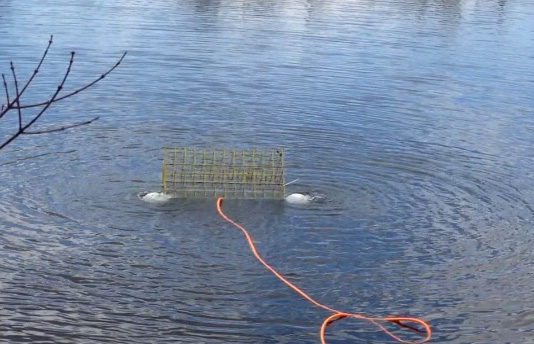
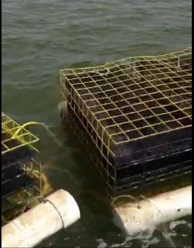
- Figure 5. Two cages with the airlift system installed connected in series floating at the surface.
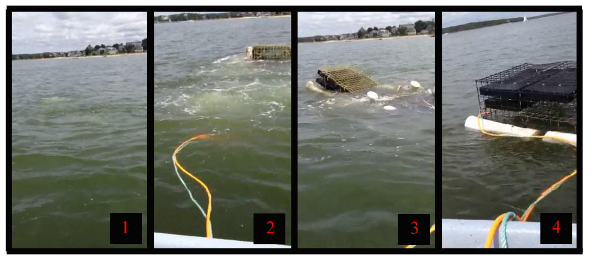
- Figure 7. Steps 1-4 in raising a cage to the surface. 1. Air pushes the water out of the PVC tubes, 2. One cage begins to rise, 3. Multiple cages are coming to the surface at once, 4. All three cages are at the surface and stable.
- Figure 10. Jordan Ward (summer research assistant) switching out the 120lb. battery which powered the two submersible pumps within the underwater upweller. Black cable leads from the battery down to the pumps; orange airline also leads to the upweller to lift it to the surface with the same airlift system as objective 1.
- Figure 2. Oyster cage used for deep water oyster culture. Dimensions are 63”Lx36”Wx18”H
- Figure 3. Typical oyster cage with float modifications being lifted using SCUBA tanks on the boat.
- Figure 8. Inside of underwater upweller with lid open. 6” windows fitted with 9mm ADPI mesh across the whole length on both sides (upper part of picture). Vinyl-coated mesh shelf to hold spat bags off the bottom (white mesh in center of picture). Orange 1.5mm mesh over the two pumps with plastic tubing pulling water to the exterior of the upweller (central in picture). Blue and orange lines leading to and from manifold in center of upweller to lift the cage to the surface.
- Figure 9. 225a/h battery in watertight box. Orange airline leading to the system and black battery cable leading to the two submersible pumps in the upweller.
- Figure 11. Underwater upweller floating on the surface with lid open.
- Figure 6. Using SCUBA tanks to put air into the system. 1. Airline with ball valve leading to the cages, 2. SCUBA tank with modified first-stage regulator to lower tank pressure to 150psi.
Air-assisted cage lift system
The proposed project included constructing five cages with the air-lift system, however due to costs associated with the multiple iterations of the design prior to implementation, only three cages were built. The three cages were completed in May 2012 and deployed when the oyster seed was delivered in early July. The cages and the oysters in the cages were treated the same as the normal cages which were accessed through SCUBA. In June, all oysters were checked and cleaned every two days. From July through September as the oysters grew the maintenance moved to once every two weeks. Of the 100,000, 6mm oysters that were purchased in July, 50,000 (initially 2L per bag, 5 bags total) were put in bags in the airlift system, and 50,000 were put in bags within the normal SCUBA accessible cages. As the oysters grew they were thinned out and put into larger size mesh bags, increasing to a total of 49 bags by the end of September.
There was no difference in growth or survival between the two systems. Survival overall was high until the annual bloom of the diatom Cochlodinium polykrikoides from the beginning of August until approximately September 15th. The diatom bloom impacted the oysters that were purchased for this portion of the project more than the oysters that were purchased for the airlift system for some unknown reason. They were from a different strain and hatchery, and strain tolerances should be further investigated. Again, although survival decreased following the diatom bloom, there was equal mortality on both systems.
The time required to access, clean and grade the oysters within both systems was also tracked throughout the entire project period from July until September. Initially as there were only 5 bags in each system, the time required to service each system was similar. It took approximately 15 minutes to dive, grab 5 bags and bring them back to the float to work. Including putting them back down that is a total of 30 minutes. Using the airlift system was much quicker. Approximately 30 seconds to bring the system to the surface, 3 minutes to bring the bags into the boat and then disconnect the airline to let them sink back down. Including putting the bags back down that is a total of 7 minutes, or a time savings of 76%. As the number of bags increased to 24 per system, the time savings relative to normal SCUBA operations remained similar. By diving, the time needed to string 25 bags and bring them to the float approached 30 minutes each way. While the airlift system still only took 30 seconds to bring to the surface and the time needed to get the bags was only increased to approximately 7 minutes, each way. This resulted in a time savings later in the project of 75%.
Given the limitations of working light and pay requirements, the more time that can be saved will lead to greater farm economic viability. However, although time savings of 75% are excellent, there are both initial and reoccurring costs associated with the system. When servicing the oysters on the typical SCUBA system, one tank of air could last at least one whole day if not more. However, when using the airlift system, due to inefficiencies in air loss, typically one tank of air would be used to bring up the series of three cages each time. At between $6-8 per fill, the requirement of 2 tanks per day (one to bring them up initially, one to bring them up to put the bags back down again) is considerable. This also does not take into account the time and effort needed to go and fill the tanks more often at the dive shop due to using the air quicker. Also, the cages would not always fall back into the same place perfectly, which could require diving to put them back in the same place. The actual economics of building the cages is in the section below.
Underwater upweller
The most important aspects to quantify for the underwater upweller systems were growth, survival and how those two indices relate to cost. Since it is not currently possible to use upwellers in Falmouth, it was not possible to compare the underwater upweller system to current upweller techniques. Growers in deep-water aquaculture currently have to buy either small seed, and accept high predation and slow growth, or buy larger seed and accept the higher cost.
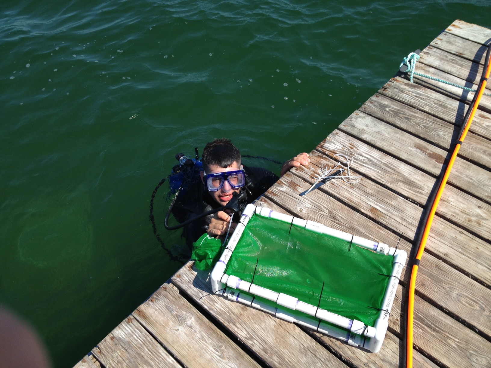
In the first week of June, 250,000 1.5mm oysters were purchased and distributed equally to four 0.75mm spat bags within ¾” PVC cube housings (Fig. 12). Two bags were put inside a normal cage, and two bags were attached to the metal shelf in the underwater upweller. The pumps were turned on and all oysters were checked and the bags cleaned every two days. Survival and shell length measurements were taken every seven days.
For the first two weeks after stocking the juvenile oysters survival and growth were equal until the water temperatures warmed up around June 20th. After that point the growth of the oysters in the normal cage outside of the upweller was actually higher than the upweller system (Fig. 13). At the two week sampling, the oysters that were larger than 1.5mm were graded out and moved to the next size mesh bag larger, and the smaller oysters were tracked separately. While at the two week mark the smaller oysters (<1.5mm) in both systems were almost the same, once the larger oysters were separated, the oysters in the normal cage system increased dramatically, while the oysters in the upweller remained close to the same size. By July 7th the upweller system was clearly inferior and so all of the oysters were moved to the standard cages.
Survival for both systems was approximately the same (Fig. 15). The oysters raised in the upweller system had slightly better survival through the five week sampling period, though by the end of the five week period of tracking the survival was approximately the same. The survival difference was never significant, and any mortality in either system was not due to predation. There were never any predators observed near or in either system. The difference in growth can be explained by a lack of food in the upweller system instead of increased food, unfortunately. Dock-based normal upwellers are moving water at approximately 900 gallons per minute. Granted, they are moving that water by many more oysters and bays, but even if it is a six-bay system, that is still 150 gpm per bay, which would have approximately the same number of oysters stocked for this project. In contrast the pumps that would work for the limited battery power given in this project were increasing water flow over ambient by 200 gallons per hour. While this increased water flow helped, it did not make up for the lack of flow due to being in a semi-enclosed structure. Therefore, the oysters in this system actually received less flow and food than the oysters just left in the standard cage.
The underwater upweller system worked exactly as planned, and did a great job at sheltering the oysters from any predators. The only drawback was the lack of power which dictated the reduction in pumping power. If there was a way to either connect to shore power, or have solar panels recharging the batteries that would allow for the upgrading of the pumps, the system would most likely function exactly like a dock-based normal upweller system, while still allowing subtidal aquaculturists to adhere to current guidelines.
Airlift system
As mentioned earlier, depending on how many bags are needed to be moved and how many oysters are lifted with the airlift system, the time savings can be approximately 75% by using the airlift system instead of SCUBA. While this is a significant time savings, it does not take into account the tank fill costs ($6-8 per tank) and the fact that it takes twice as many tanks to service the oysters in the airlift system as compared to normal SCUBA operations. However, by using the airlift system, the process can be completed entirely above the surface, which means no wetsuit, and reduced danger from diving potentially alone. To anyone who has dove in the winter or spring in New England, the appeal of this cannot be overstated! So although the reoccurring costs may be similar, the advantage to not having to actually get in the water, and the ability to work alone brings about many advantages.
In addition to reoccurring costs due to tank fills, there are the initial start up costs associated with building the system on each individual cage. As the process of building the system went on, I continuously made sure that any purchases or designs had the absolute minimal addition of costs in mind. There are clearly ways to make the entire system more robust, though any additional modifications would add significant costs as well. The initial design had more expensive valves and manifolds, which I was able to switch out on the final iteration. I also bought 6” PVC fittings in bulk whenever possible to reduce costs, however the additional costs to implement the airlift system per cage are still significant. Each cage costs an additional $160 to outfit with the system, above normal construction costs to build the 3” wire mesh cage. Clearly, if this was to be implemented on a wider scale costs savings could be realized from bulk purchases. Over half of the $160 cost is due to 6” PVC and 6”PVC fittings which are very expensive. If there was a way to buy PVC in bulk, and switch brass barbs for plastic ones, the price per cage could come down significantly.
Underwater upweller
Not including false starts in the design, the underwater upweller system cost approximately $150 to build, and it worked very well for what it was designed to do. The real costs associated with the upweller were the batteries and container to hold them. For the two batteries (to have one charging while utilizing the other one) and watertight container, the cost was over $1400. Each battery was over $500, and they still would only last for 3-4 days. Clearly with the reduced growth there is no reason to implement the system as is. The pumps would need to be upgraded, which would require another power source. The batteries purchased for this project were the biggest commercially available, and they still were not big enough. In the future the underwater upwellers will need to have an alternative power source other than merely batteries with no real-time recharging source.
Farm conditions were similar to other subtidal farms in Falmouth and throughout Buzzard’s Bay throughout the entire project. I do not believe they had any effect on the results that were not equally distributed for all oysters in the compared systems.
- Figure 13. Length of oysters that were greater than 1.5mm after 2 weeks and therefore were moved to bigger size mesh bags.
- Figure 15. Survival over the 5 week period of comparison between oysters raised in the upweller compared to the oysters raised in the normal cage setup. The upweller had slightly better survival for most of the 5 weeks, though by the end of the sampling period the survival was approximately equal.
- Figure 14. Length of oysters that were less than 1.5mm at the two week sampling period. They were kept separate from the larger oysters at that point and were tracked separately.
- Figure 12. ¾” PVC cube with 0.75mm oyster spat bag attached.
The airlift system was constructed and implemented on three cages in July 2012, and was operational for the entire growing season. The time savings were significant, and led to increased safety on the farm by not having to SCUBA dive in order to work on the shellfish. The design process took approximately 6 months, and included many iterations of floating mechanisms before a final design was reached. The final design that was decided on had to be both efficient for the farmer, able to be constructed easily with minimal costs and had to result in significant time and safety gains for the farmer. The design which was decided on fit all of those criteria, and if implemented on a wide scale could change the manner in which oysters are farmed in New England. The underwater upweller system was also revolutionary in design, and with minor modifications has the ability to also greatly benefit subtidal shellfish farmers throughout the region. The design process for the upweller also took approximately 6 months, and also required constant changes and optimization as the process moved along. The final design that was implemented resulted in a new method which fits within all current aquaculture guidelines, though as it is currently implemented does not result in growth and survival gains. Power limitations can be easily overcome through either shore power, or solar arrays, however that was outside the scope of the current project. Future research will evaluate cost savings and efficiency gains through power increases, which have the potential to result in real cost savings and productivity gains for aquaculturists.
Education & outreach activities and participation summary
Participation summary:
The Cape Cod Cooperative Extension (CCCE) is the education department for Barnstable County, and has been assisting with the implementation and outreach component of this project. The Fisheries and Aquaculture Specialist for CCCE and Woods Hole Sea Grant, Diane Murphy, has suggested several methods by which the results of this project could be made known to farmers in Cape Cod specifically. I have presented the results in a poster at the bi-annual conference Northeastern Aquaculture Conference and Expo, held in Groton, CT, December 12-15 2012. I will also present the results at farmer workshops held by CCCE, and MAA (MA Aquaculture Association), as well as at the CCCE 8-week course “Fundamentals of Shellfish Farming,” held every other year in Cape Cod, upcoming in the spring 2013. I am a member of the Falmouth Shellfish Cooperative (FSC), which incorporates 4 of the working shellfish farms in Falmouth. The group meets monthly, and works together to purchase seed, cages, and has collaborated with Coonamessett Farms, in Hatchville, MA, to purchase a refrigerated truck for shipping, and build a centralized refrigerated holding area for the oysters prior to sale. I have discussed all results from the project to the other farmers in the area currently using SCUBA or the mechanical hauler method.
Project Outcomes
Potential Contributions
The airlift system has the potential to result in significant time savings for subtidal farmers in New England. There are several drawbacks to implementing the system as it currently is designed, though the limitations can easily be overcome. For instance, the $160 cost per cage to install the system is too high to be integrated into most aquaculture ventures. One of the goals of this project was to design a system which would reduce start up costs for new farmers, and if the price per cage is doubled, that is not a sustainable system. However, if a cage manufacturer or investor wanted to take the design and buy the products in bulk, significant savings could be realized. Also, by purchasing HDPE instead of PVC, prices per cage could also come down. Another drawback was the large amount of air needed to raise the cages, and therefore the multiple SCUBA tanks needed to use the system. However, if other aquaculturists simply had an air compressor on their boat, the need for SCUBA tanks could be eliminated altogether. The system works excellent, and can result in a meaningful improvement in current culture techniques.
The underwater upweller system also provided a step forward in subtidal shellfish culture, though significant improvements must be made for the system to be implemented in the future. The aspect of complying with current aquaculture guidelines, while protecting and increasing food to the oyster seed will benefit and interest many shellfish farmers. However, in this particular project the lack of power dictated smaller pumps than are optimal, therefore limiting growth throughout the sampling period. Future research can focus on increasing power through solar arrays, or if other sites are better suited, bring shore power to the upweller, which will allow for an increase in pumping power. The technique demonstrated through this project is a first step in modifying current intertidal shellfish upweller systems to be used on subtidal farms, which is where the shellfish industry in New England is moving. Future research can take the current design and optimize it for optimal growth and survival, which can significantly benefit aquaculturists throughout the region.
Future Recommendations
I plan on continuing to use the three cages which have the airlift system attached, and would like to expand the airlift system to additional cages on my farm. The additional cost per cage is significant however, so it would be cost prohibitive to expand the use of the airlift system alone. I will continue to discuss the advantages of the system with other farmers and hopefully by getting other farmers to want to use the system as well, bulk purchases can be made, bringing down the cost overall. The upweller system as it currently operates is not feasible and does not help operations. However, I do believe the design is sound, the limiting aspect is power. I plan on researching optimization of the underwater upweller in the future and I will apply for funds to do so. If there is a way to incorporate solar panels or shore power into the system the gains in both growth and survival could be excellent.