Final report for FNE19-937
Project Information
I sought to develop a means of building small-scale processing facilities in a way that made their implementation less cumbersome for farmers. I knew that there are so many overlapping needs with such facilities that long-term cost and ease-of-implementation gains could be achieved using modular building methods. My work began with shipping containers, drawn at first to their low-cost and availability, then discouraged by their lack of flexibility in multi-section designs. I developed a means of designing units or modules from wood construction that offers more design freedom and positive local supply chain impacts. I composed a summary report provided with this SARE submission that clearly illustrates how effective this construction approach could become in the deployment of small, safe, productive agricultural workspaces. I also shed light on how this construction approach could form a strong synergy with small sawmill operations with planing and shaping capabilities. Outreach at this stage has been limited to farm tours to interested parties, local legislators, and neighboring farmers. Once the meat processing facility is complete, larger organized events will be feasible and beneficial. A dedicated website for The Locust Works and the MMP design is being constructed at this time. Anyone interested in this work is encouraged to contact me.
This project sought to determine the impact of an on-farm modular constructed meat processing facility on the profitability and viability for local livestock farmers.
Objective 1: To complete the construction of the prototype modular facility and beginning operation under USDA inspection in order to demonstrate the increased profit possible for beef farmers in slaughter, processing and packing costs of this crucial step for small livestock farmers.
Objective 2: To track design, material and labor costs for the project which will analyze the changes in processing costs between a local commercial slaughterhouse and our on-farm modular process.
Objective 3: To design a web based open-source design offering farmers the components of a proven, diversified modular on-farm processing facility as an expansion opportunity for beef farms.
On-farm butchering provides an opportunity for farm families to earn a happy, productive life on the farm. If we make it a goal to empower family farms with processing technology, we take a step toward regenerating positive, meaningful work into our agricultural communities.
Local livestock farm's infrastructure needs are significant, but not overly complex. We need access to good pasture and water, suitable barn space for harsh weather, and corral(s) for safe handling. Access to skilled slaughtering, packaging and secondary processing facility is a costly bottleneck for many farmers. Adding walk-in coolers and freezers for finished product, a vehicle with cold-storage for large shipments and some warehouse space for packing CSA and web-orders is also essential for value-added meat sales. Most local farmers operate without several of these key elements, driving their logistical burdens in excess of what is manageable or profitable.
Many have the idea that if they can just “make do” with chest freezers and several hours of driving for every beef they process off farm, that they can gradually improve with time. In my experience, the margins in the business do not support this approach. Typical butchering processing costs in the Northeast are well over $2/lb. of packaged product. When farm costs of field production are $3.5 to $4/lb. to raise a beef, the margins start to look very slim. Even at an added-value price point that Grass-Fed Beef brings at an estimated $7/lb., it doesn’t leave much margin for profit. The same is true for meat from other livestock species. We are essentially producing a commodity item in a highly inefficient manner.
Naturally, it becomes clear that every local meat producer must carve out a niche and find clever ways to add more value. Smoked and cured meats, prepared foods, on-farm burger nights are all ways to drive up the value of our products. However, this is where we reach our second impasse. As difficult as it is to book slaughter dates in the Northeast, it is even more difficult to gain access to the smokers, curing ovens and commercial kitchens needed for the value-adding. If we do find access to such facilities, it is almost assured that there will be several more hours of driving involved per batch; on-top of the travel hours of driving for the one or two beef to go to slaughter. Then even more hours driving to pick up the boxed meat when it is ready. The carbon footprint of this approach is unacceptable. The only reason why farmers are faithfully running this gauntlet is the firm belief that they are doing the right thing for their families, their animals and the mouths they feed. The meat undoubtedly tastes better and it is better for you.
This is where open-source engineering and the notion of information sharing can have tremendous impact. The construction of the basic elements needed for on-farming slaughter can be well documented and openly shared. If farmers had access to plans and “build-kits”, they could build or purchase one section of their facility at a time, minimizing upfront capital outlay and avoiding the hamstring effect of cobbling together poorly planned and constructed systems.
Little has been done to organize and streamline the construction of small livestock meat processing facilities in the Northeast. There were efforts to construct and implement mobile processing facilities to serve multiple farms. However, a majority of those processors developed in the early 2000’s were for poultry.
A limited number of mobile processors were for beef. One such Moduler Harvest System was implemented by the Glynwood Center in Cold Spring NY for a brief period of time but proved to be overly cumbersome and has been shut down. A dedicated mobile beef processing facility was operated by Green Pasture Meats of New Haven VT but has closed the mobile slaughterhouse and meat market as of 2018. Adams 5th Generation Farm in Wilmington, VT was a meat business with an on-farm facility, but that has also just closed.
At this time there are no on-farm USDA inspected beef processing facilities in Vermont. Several mobile slaughter and processing units for poultry farms are now in operation around the country. However, on-farm processing for beef and hogs is considerably more challenging. This, however, does not mean that the concept of on-farm slaughter is not feasible or viable. It just means that the process of constructing the facilities is deterring many farmers from successfully continuing those mobile types of operations for large farm animals in the northeast.
We can look to a small dairy supply business operating in New York for inspiration. Don's Dairy Supply of South Kortright, NY offers farmers a turn-key Public Milk Ordinance Approved Creamery unit constructed from a re-purposed shipping container. The unit comes fully equipped with processing and sanitation equipment, putting their farmer customers on a fast track to value adding. The current price for a base bottling creamery is $58,000, which is essentially the material cost for an equivalent stick-built facility before factoring in planning and construction labor. Don's Dairy Supply clearly learned what I have also learned in my experience with modular building and that is there are dramatic savings in cost and complexity through duplication and repetition.
According to VT Farm to Place’s “Grass Fed Beef Value Chain Research”, the four largest beef processing facilities in the USA can not only streamline production costs to about $100 per beef animal, but significantly undercut regional and local processors on processing fees. In Vermont, it can cost processors up to $800 to process, finish and deliver a beef animal. By operating an on-farm USDA approved craft butchering operation, a small farmer can reclaim a large portion of their processing costs as value-added income.
This project aims to make it very easy to construct an on-farm modular meat processing facility initially with a focus on beef and swine. Prior efforts have been made to offer meat producers more access than commercial slaughterhouses through mobile facilities. Over the past 15 years, there were a few successful mobile facilities for beef in the far Northwest. But we have not found any USDA approved on-farm modular facilities in the Northeast according to www.eXtension.org on small meat processing facilities.
My project is novel in that it is focused on empowering farmers to do their own skilled butchering. As a local meat farmer, I have developed a strong understanding of what is needed for a small, local meat business to operate. This project aims to find commonalities in the basic requirements for the local meat farms, and to weave those common threads into a streamlined system of sequential business development opportunities.
Brian Leach, BSME will carry out the design, construction and operation of the proposed facility. He is the owner/operator of Haystack Farmstead which is a grazing beef operation and The Locust Works, an engineering and manufacturing facility located on the farm. Brian is trained as a mechanical design engineer, with a focus on system design and fabrication. For the last 10 years he has been investing in the infrastructure needed to construct value-adding facilities to support local agriculture. His career goals are to provide young farmers with pathways to success and to demonstrate the impact of technological empowerment as a counter-mechanism to rural stagnation.
Cooperators
- - Technical Advisor
Research
2020 Progress:
Several design sessions were committed to ironing out the details of the container conversions. As shown below, I have previously created a detailed Computer Aided Drafting (CAD) model of a ISO-standardized shipping container that serves as a blank slate for creating a functional workspace.
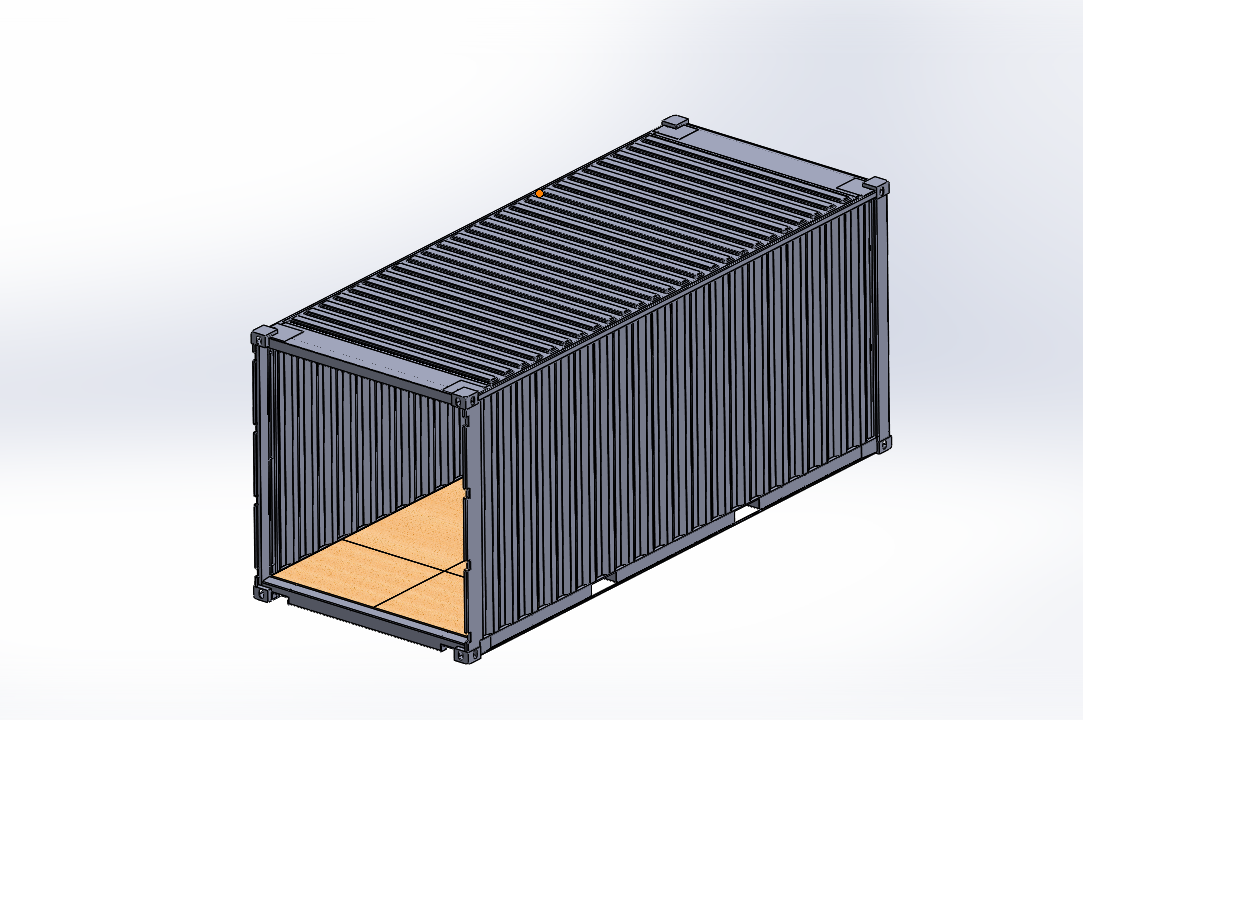
The challenge comes in modifying the rugged skeleton of a container into a space that has all the elements of a functioning shelter. Insulation, drainage, power, windows, doors and techniques to combine containers are all modifications that require planning and improvement with time. During the summer and fall of 2020, time was spent developing a first-pass at what will eventually become a set of standard conversion methods. The methods are sketched out on paper (see below) prior to transitioning to CAD.
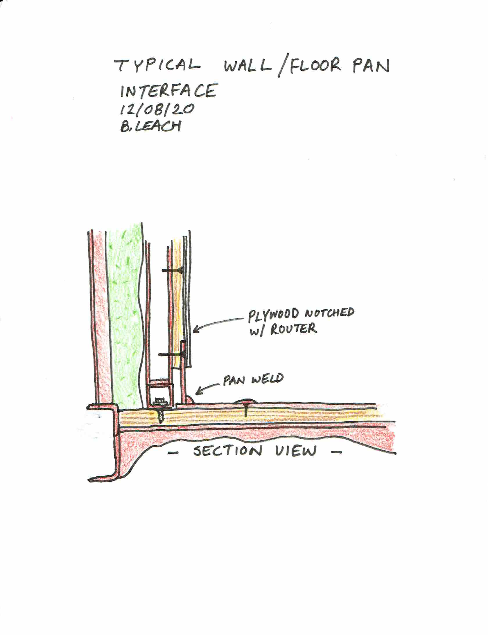
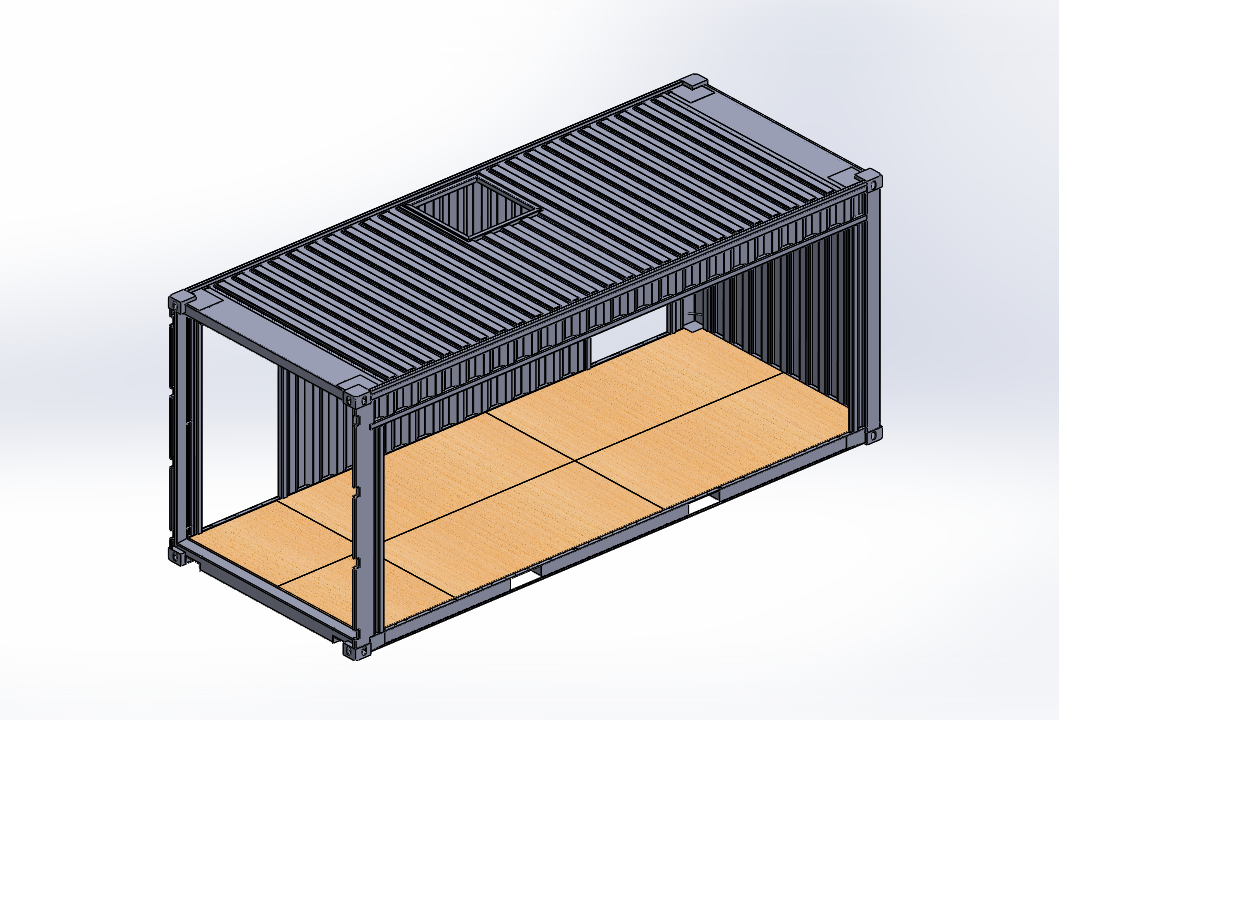
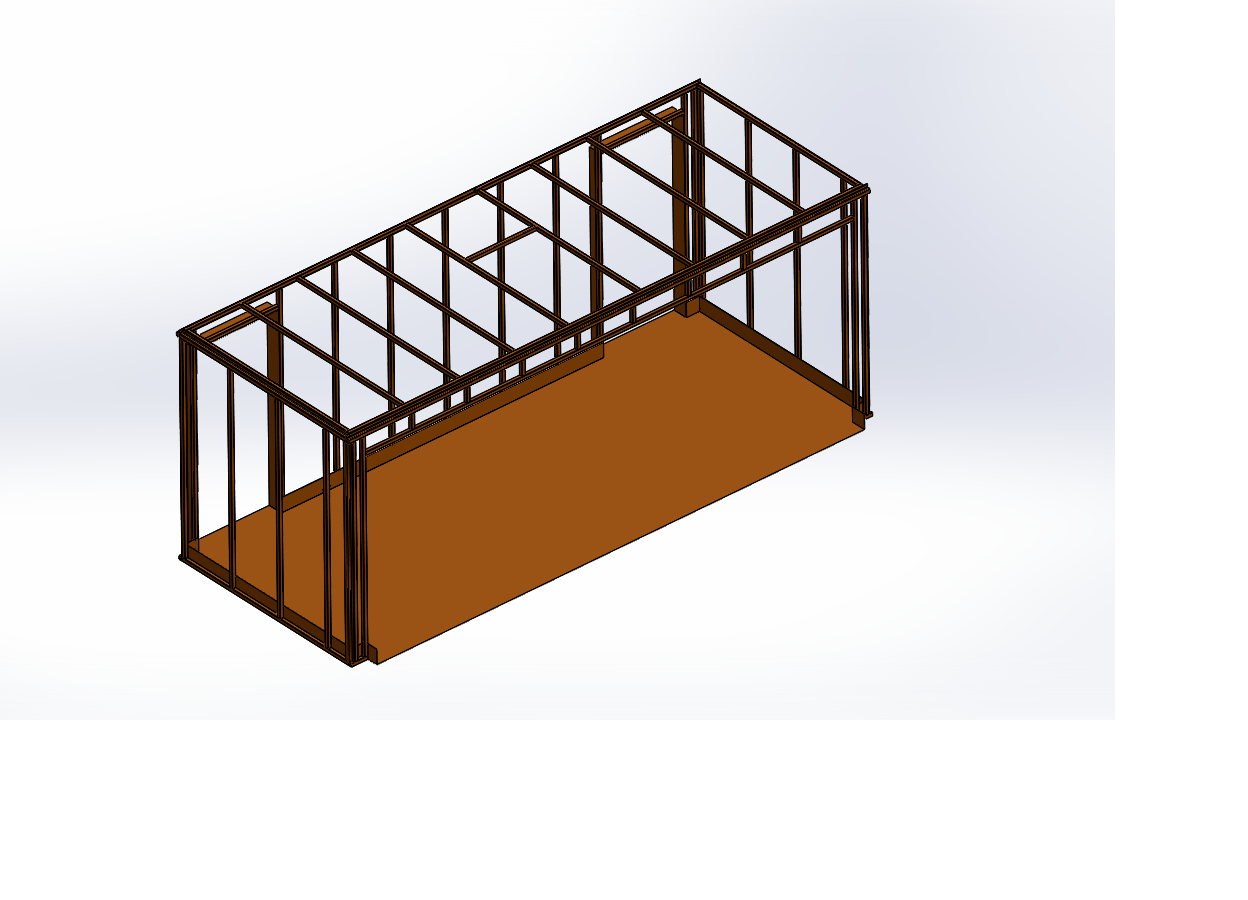
The first pass of the Standard Conversion Method sufficiently established, the layout of the MMP can be executed in CAD. The major components of each section include a shell that is the container's modified envelope, an interior frame skeleton for mounting the interior walls and a sheet metal floor pan. Examples are shown below:
In the fall of 2020, the following facility layout was discussed with personnel within Vermont Agency of Ag. The feasibility of the plant layout was confirmed, meaning detailed design work could continue.

During December of 2020, work focused on translating the layout discussed with the state into a detailed CAD model that will be used to generate blueprints for the 2021 build. As shown in the image below, the design combines two containers to generate an open floor-plan. The steel removed from the wall cuts will be re-used to form a cupola that provides the needed overhead space to lift a beef carcass for necessary kill floor operations. A section view of the facility sections as they are currently modeled is shown below:

2020 Conclusions: Significant design progress has been made on this project. Prior to ordering containers and steel, the carcass cooler section depicted in the layout sketch needs to be modeled which should be completed by February 2021. Spring and Summer '21 will be dedicated to the actual build.
2021 Progress:
It was determined in 2021 that more significant fundraising would be required to complete the project. When the MMP was proposed, Brian hoped he could use available funds from farm revenue to cover the materials budget so that the system could be built one step at a time. This has proven to be an ineffective strategy due to both time and monetary constraints. The project strategy was revised and can be summarized as follows:
- Raise more funds so that supplemental skilled contract labor can be brought in to assist with the build
- Involve other farmers more directly with a cooperative development and management model
- Increase planned productivity of facility to allow for a portion of the project to be financed with an appropriate rate of return
An application to the Vermont Working Lands Business Grant program was submitted and denied in early 2021. However, it was announced that a Meat Processing-Specific Working Lands opportunity was forthcoming in Fall of 2021. Anticipating this, outreach to neighboring farms and contractors was conducted to assemble a cohort and detailed project proposal. An application was presented to the Working Lands Enterprise Board that included the same proposed facility as outlined in this project, but with specific plans to operate the facility with other farmers. A hands-on training program for the farmer management group was arranged with existing USDA-inspected slaughterhouse Higley Hill Processing in Wilmington. Pre-approval for $30k of financing was obtained through RFN Capital.
Total budget request was for $95,259 which will complement $24,000 of existing grant cash commitments and $30,000 of financing.
Notification was received on 1/02/2022 that funding to the project was awarded.
The Enterprise Plan for the project is linked below and includes key planning charts:
HF_MMP_Enterprise_Plan_Sheets_Included
Research Updates: Final Report December 31st, 2022
As planning began to resume work in the Spring of 2022, it was decided to abandon the use of shipping containers and instead develop a modular building scheme centered around locally milled lumber products. This decision was driven by discussions with UVM Extension regarding potential synergies that exist with small-scale farming and forestry. It was also partly driven by a dramatic decrease in shipping container availability resulting from supply chain disruptions. My first-hand experience converting two shipping containers showed that it was very much feasible to do so, but the more variation a design demanded, the more limiting the use of shipping containers became. Designing a facility to handle is one of the more challenging scenarios for a small-scale processing facility: Bleeding cattle requires 16' (4.88 m) ceilings and recommended carcass cooler rail height is ca. 12' (3.66 m). My prior design using the shipping container approach featured a cupola with a fixed position hoist. This would have delivered adequate productivity, but transitioning the carcass to an adjacent high-cooler was not feasible without lowering the carcass and then raising it again. The shift in 2022 was to a Modular Timber Frame (MTF) design that offers more ceiling-height flexibility which I will discuss in detail.
2022 UPDATED DESIGN GOALS
- Develop a "turn-key" meat processing facility that can be built at a specialized construction shop and delivered in sections without over-width or over-height permitting requirements in continental US. This translates to transport width limit of 8'6" (2.59 m) and height limit of 10' (3.05 m)
- Use local rough-sawn, kiln-dried, milled to custom dimension, softwood lumber for all framing and sheathing.
- Design all key features such as windows, doors, skylights, hoists in a manner that supports local manufacturing - Design for Manufacturing and Assembly (DFMA-Local)
There are multiple layers of development with this project. The highest being the "food systems view", in which the Modular Ag Processing System (ModAPS) is a component of the future farm landscape in which every small-holding is home to some form of agricultural processing; be it meat, flour, biofuel, wood-products manufacturing, etc. It's an admittedly Utopian ambition, but it never hurts to have a positive general trajectory.
At a layer below that system context is the development of ModAPS - The actual build and installation system for the before-mentioned production spaces. This aims to be a flexible approach that enables different systems to be built from common elements. If a small-scale creamery requires a 16' (4.88m) square processing area with wash-down walls and drained floors, that's great because it's the same as a small meat fabrication area or commercial kitchen space. The benefit of this overlap is most apparent design and manufacturing side of things. It doesn't cost much more for a shop to make slightly different versions of the same thing. On the end-user side, the value is observed as system maturity and quality. A farmer can implement a biochar generation facility that is unique to their needs and yet benefit from all the build repetitions of different systems. MAPS can be compared to a popular plastic interconnecting block building set for children. The position of the little interlocking circles and dimensions of the blocks give kids the ability to build what they want.
At a layer below the Modular Ag Processing System (ModAPS) is the design of the Modular Meat Plant (MMP) here at Haystack Farmstead. It is an agricultural processing system built with ModAPS. This project is particularly challenging because it is akin to asking a child that wants to build a pirate ship from plastic blocks to first design an interconnection and patterning standard and then machine the injection molds to manufacture the blocks. It has felt overwhelming at times, but the conceptualization of the above "system layers" has been a helpful abstraction.
Developing the "Core and Cladding" Model
I made the decision to commit to standard unit ship-width to improve transportation logistics on a per-unit basis as is the case with shipping containers. Sticking to 8'6" (2.59 m) transport width means that ModAPS units can ship individually on standard farm trailers, or as pairs on "step-deck" commercial truck trailers without special permitting and escorting. It's important to me to design a system that enables some amount of regional movement for young farmers. A couple that operates a micro goat dairy on leased land in Massachusetts can relocate their ModAPS-based creamery to a purchased farm in New Hampshire at reasonable expense.
Working with a relatively narrow form-factor means that wall-width utilization is critical. It also became clear that wall construction is a factor in the "forward-compatibility" of the system. Imagine a simple creamery composed of 2 units combined to form a 16' (4.88m) square processing area. Initially one or two of those outside walls will be "to the weather", and will need to be insulated accordingly. However, if the creamery is expanded and a yogurt production area is added adjacent to one of the walls that was previously to the weather, it would be nice to repurpose the insulation and siding from that old wall and move it to the outside of the new addition. These factors influenced the decision to pursue a "Core and Cladding" approach to modular unit construction.
Eventually, this line of thinking led to 5 discreet design groups that compose a typical ModAPS unit.
- Core or Frame - The primary timber frame of each module
- Interior Panels - The insulation within the frame envelope, the interior sheathing, sanitary lining and trim. Within this category, wall panels and ceiling panels are handled differently.
- Cladding - Any insulation that is outside the frame envelope and the siding
- Roof Assembly - The rafters, insulation stack, sheathing and roof-skin
- Floor Assembly - The floor joists, insulation stack, subfloor and aluminum floor pan
Detailed discussions of the finished designs of the above sub-assemblies will be offered in the attached summary report.
Discovery of the "L2W" Concept
An unexpected yet significant benefit of separating the modular build unit cores from their peripheral components is that the length dimension of the core frame can be set to exactly twice that of the overall width, enabling rooms within a ModAPS facility to be turned 90 degrees without impacting the seam locations of any of the peripheral components. Obviously it's not a complicated concept, but it is not possible with shipping containers as their overall dimensions are not even multiples. I coined the approach Length = 2 x Width as "L2W" which proved to be hugely valuable in the final layout of the MMP.
Prototype Core Frame Build
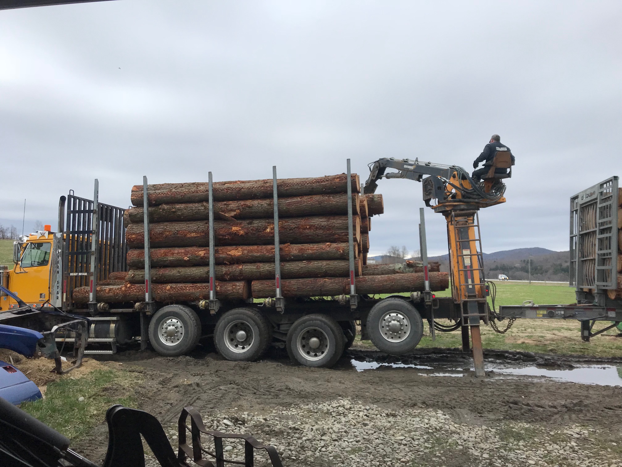
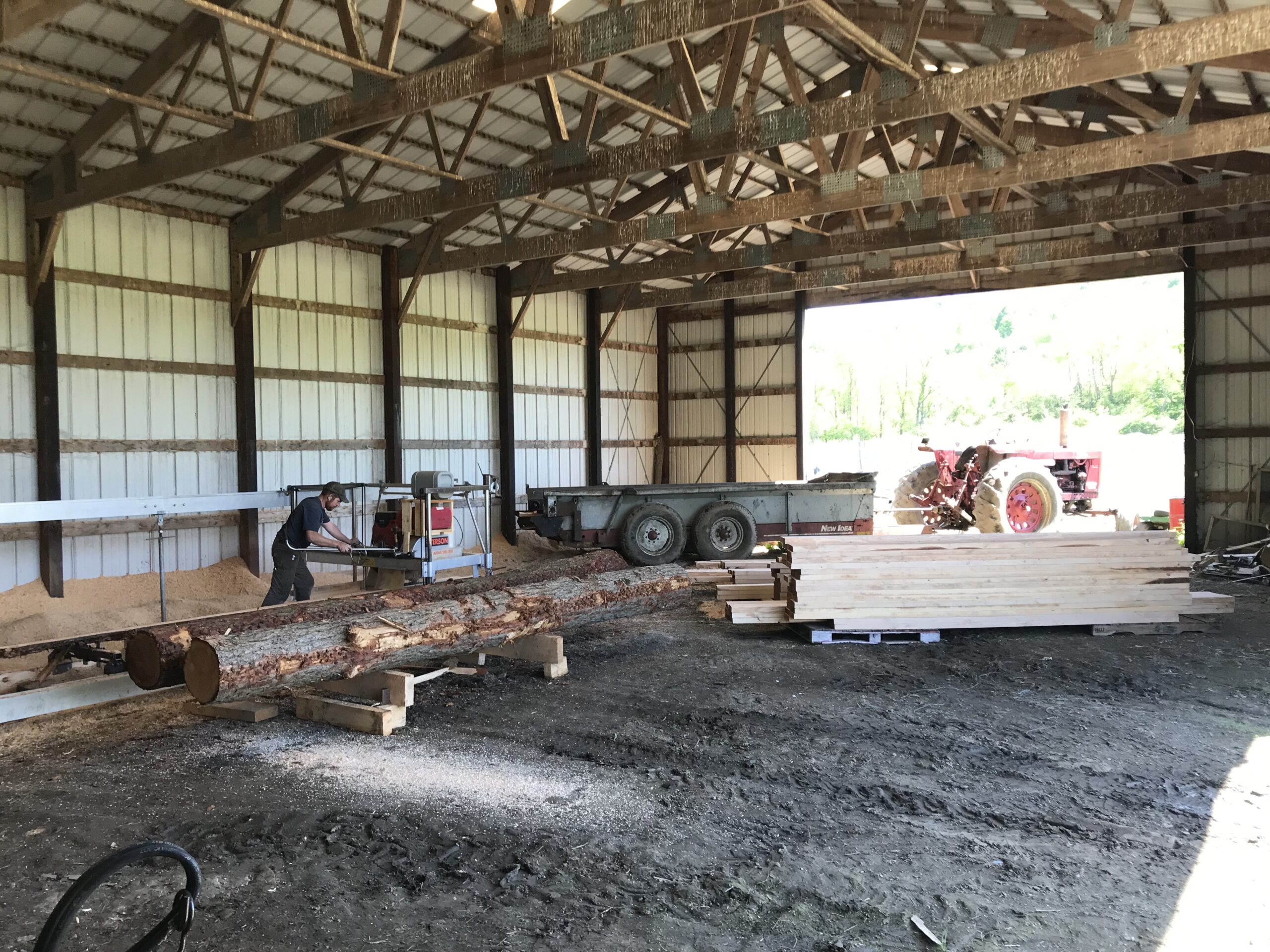
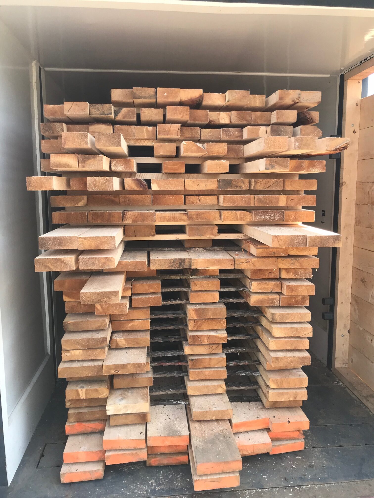
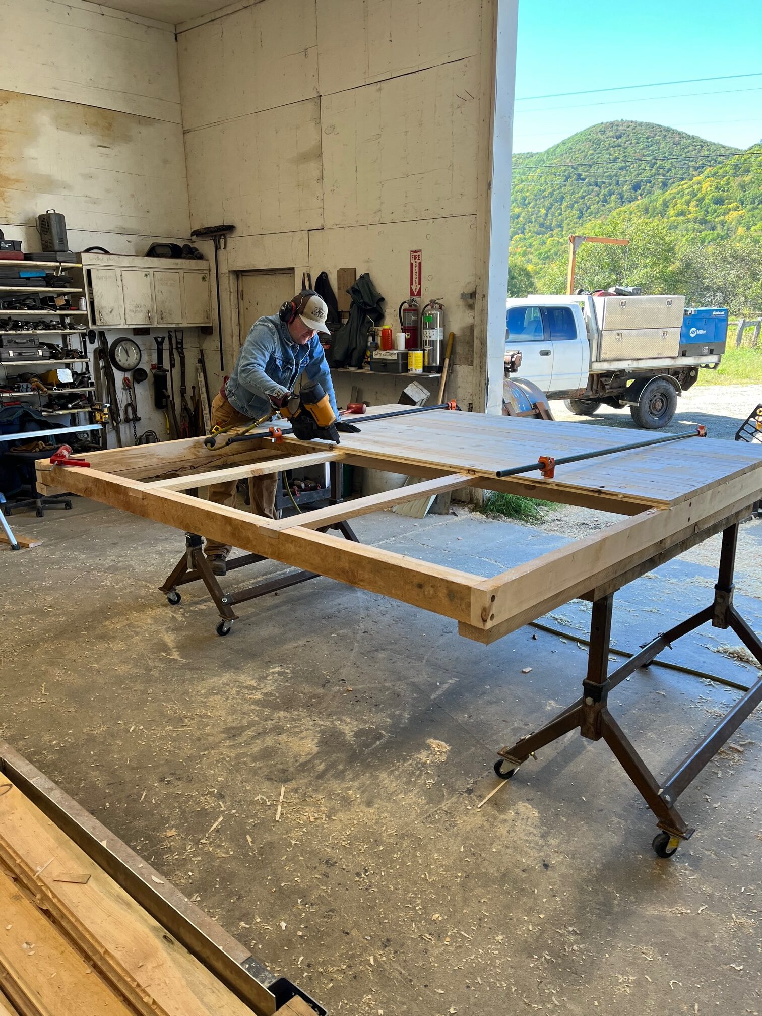
During the summer of 2022, work was started on the Core Frame of the ModAPS build modules to be used with the MMP. With general confidence in the Core and Cladding Concept and the L2W system of dimensioning, I began detailed designs of a Modular Timber Framing (MTF) scheme while a local farmer and project contractor Seth Butler set up a portable sawmill in the back of the shop area and a rudimentary low-temperature kiln that would dry the milled lumber.
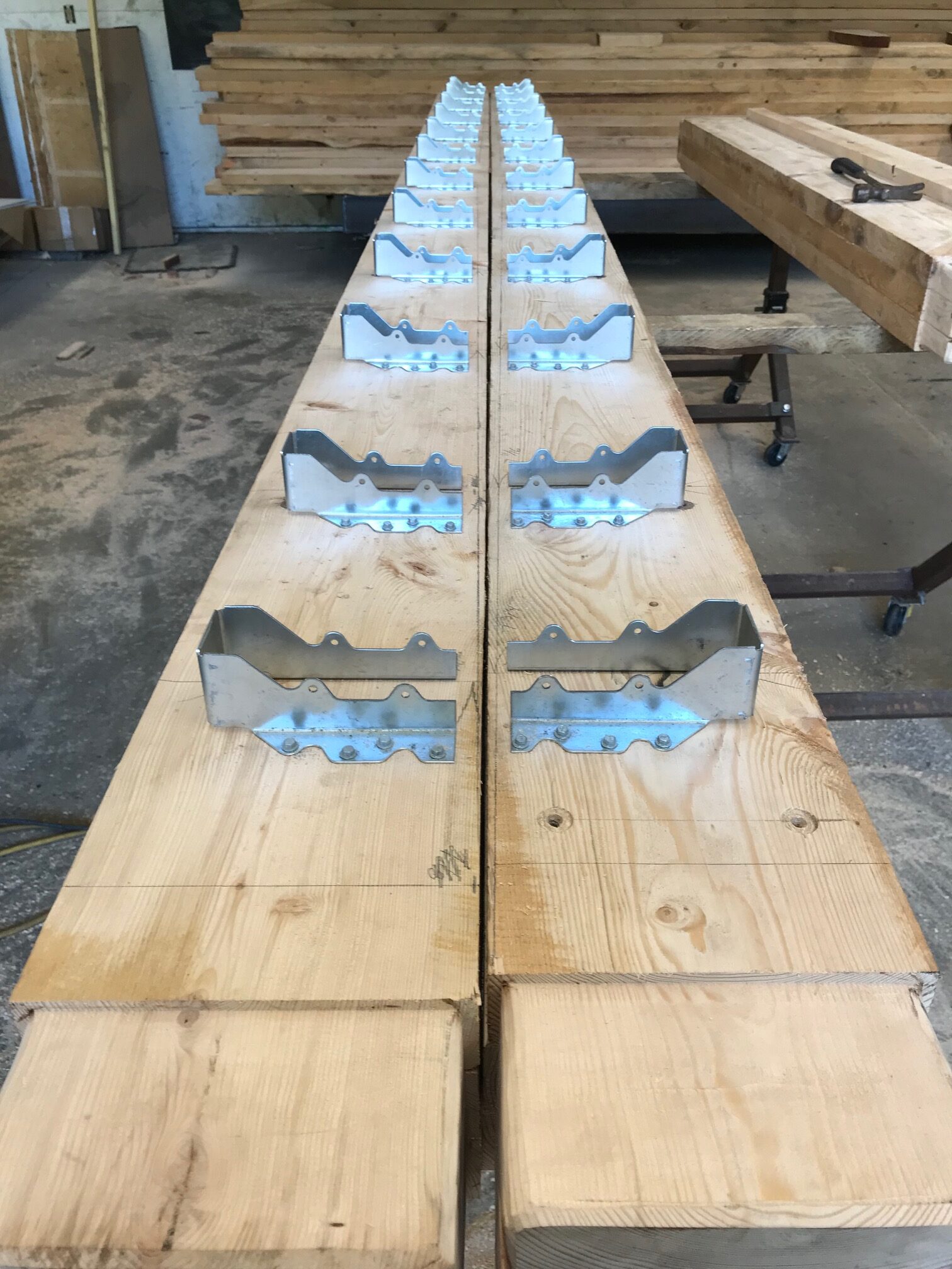
Corner Brackets
Key to the safe and rapid mobility of shipping containers are the heavy steel corner castings that are used for hoisting and restraint.
I drew inspiration from these for the design of a heavy duty corner bracket in which all 3 timbers composing a module corner "pocket" into the bracket. As shown in Figures 10 and 11, the timbers are machined on the ends to allow proper fit into the bracket. Brackets on the top corners of each build module feature a large threaded hole to receive lifting eyes for rigging. To handle modules around the shop yard, a dedicated spreader was constructed that performs a pure vertical pick on each corner. This is important for special module sections that might not have timbers on all corners and thus cannot handle resultant loads from diagonal rigging.
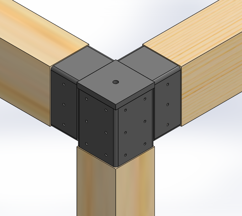
The corner bracket design enables complete transfer of beam moments in three planes. Part of the decision to design such a joint is that it reduces the shear requirements for the interior and exterior sheathing, allowing me to safely incorporate local solid-sawn products into the design. The corner bracket is a costly assembly when machined, fixtured and welded by hand. Per-unit costs for this prototype build were $325 ea. materials and labor. However, it is an excellent candidate for a small, semi-automated machining and welding production cell. If such a cell could enable brackets to be sold at ~ $100 ea., they would be a viable build-component.
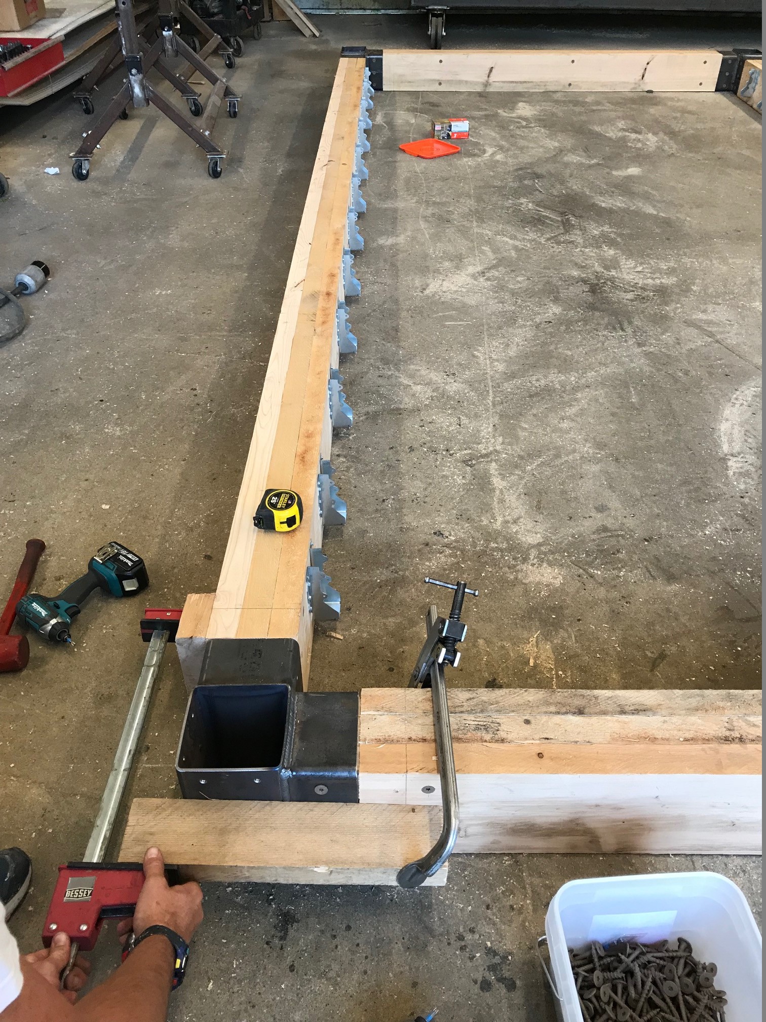
Laminated Timbers
I made the decision to size each module's roof beams to handle roof loads independent of any stud-work in the walls. This means that all walls within the structure are partition walls, offering a high degree of design flexibility and forward-compatibility. It also simplifies the wall cross-section, enabling complete sheets of insulation to be installed, meaning fewer seams and fewer draft/vapor leak paths. A critical eye will observe that the design of these top plate timbers is inefficient: The same strength could be achieved with a deeper, narrower beam, but such a choice would reduce ceiling headroom within the modules.
We employed a simplified approach to Laminated Timber construction. Modern "mass timber" component manufactures have specialized equipment to cut finger joints that enable boards to be spliced together. When the boards are stacked, pressed and glued, they can form large beams and columns of virtually any depth and length. Without such technology, we can only design members within the length limits of what's readily available by "truck and pup" trailer load. In our case that is 16' (4.88m). Therefore, our process of building the timbers was kiln-dry the lumber, plane to finish dimensions of 2" x 8" or 6" depending on the location of the timber. We then clamped the boards together and joined them together with self-drilling structural timber screws on a 16 in (40.6 cm) pattern. An advantage of the previously discussed corner bracket design is that the ends of these laminated beams are completely captured by the steel tubing perimeter of the pocket. This ensures that all three boards within the laminated timber transfer their load into the joint and the transmission of that load does not depend on a glue or fastener joint in the area of the corner. The role of the timber screws along the length of the timber is to ensure the rafter or joist loads by way of the hanger brackets are transferred into all three boards of the laminated timber and not just the inside board into which the hangers are screwed.
Roof Skin
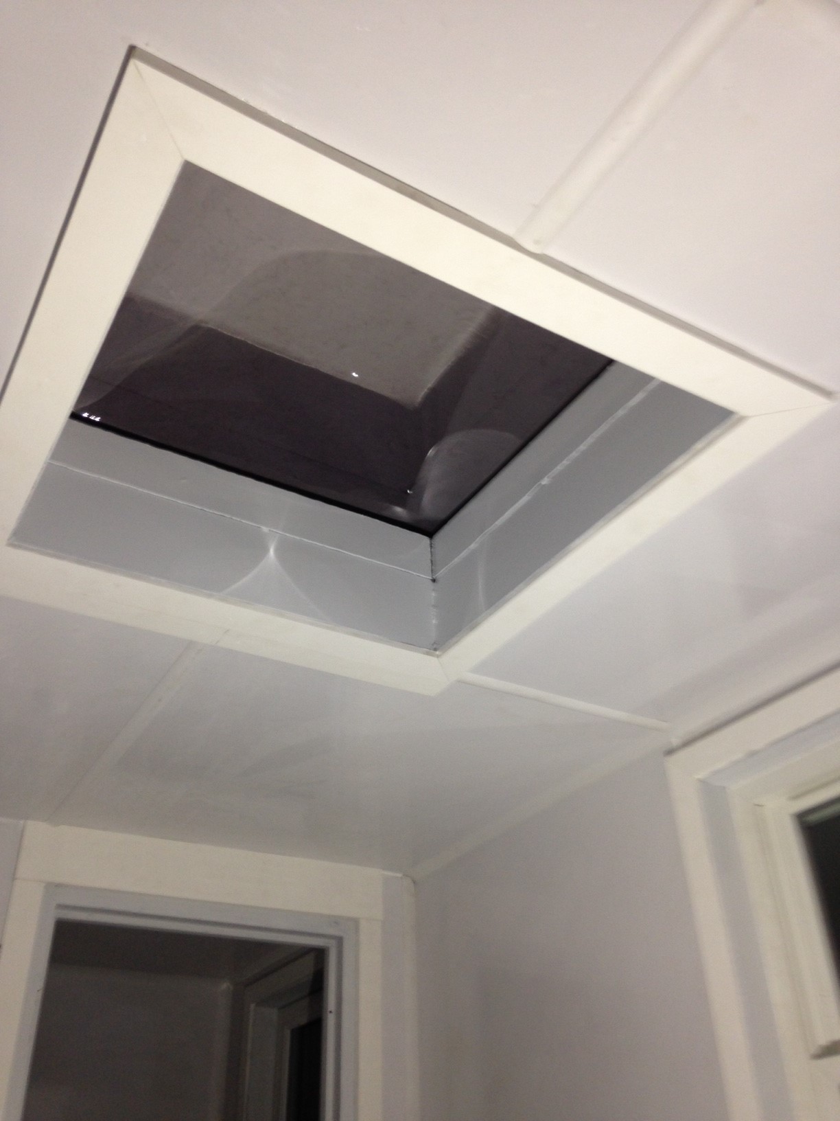
Again, inspiration was drawn from shipping containers for the design of the ModAPS roof assembly. Shipping containers employ a 16 GA roof skin with formed depressions to stiffen the membrane. I opted to employ a steel roof of the same thickness, with support for the skin coming from rafters below. Part of the motivation for pursuing this roof construction over other more conventional options was my desire to include skylights in the roof assemblies for each processing area. In my prior shipping container conversions, I experimented with skylight installation and was very pleased with the abundance of natural light and the spacious feeling imparted by the skylight (see Figure 13).
Due to overall height constraints for the ModAPS units, the roof construction is nearly flat, with a mere 4 " (10.2 cm) of pitch over 16' (4.88m). With this little pitch and with a desire to include skylight features, a fully seam-welded roof skin was chosen. Welded construction eliminates the need to install flashing at tricky areas such as inside and outside curb corners. Because the ModAPS units are built in a controlled facility in the close proximity of welding equipment, the use of this approach is deemed feasible. Further cost and longevity analysis of the method will be useful going forward.
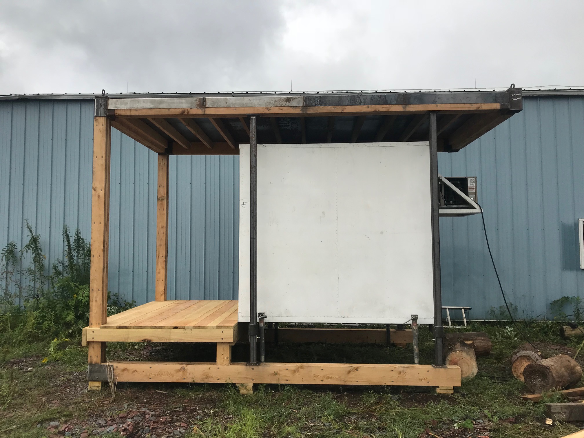
The construction of a simple shelter for an existing cold-storage unit on the farm offered a chance to build a simplified roof skin and evaluate its ease of manufacturing and functionality. The final design of the roof assemblies to be employed in the Haystack Farmstead MMP build will be discussed in the attached summary report.

Testing Load Spreader System
As mentioned, a simple structure was needed for a prior-built on-farm freezer unit. We referred to this structure as a "Reefer Dock" as the original intent of the freezer unit was for it to be readily installed and removed in under 10 minutes from the Haystack Farmstead farm truck. Completing this structure was an excellent opportunity to test out the ModAPS build methods in development, along with the dedicated load spreader. Hooking and unhooking the spreader was a simple matter. As can be seen in Figure 15, the full adjustment range of the main spreader was needed. This particular assembly is relatively asymmetric compared to the designed MMP units, but picking modules with heavy sub-components such as stun-boxes, hide pullers etc. will certainly push the center of gravity of the pick off-center. It was clear from this preliminary test that the spreader will perform as intended for setting the MMP-Haystack units.

Drained Floor Development
The final physical build component completed during the SARE research window was a prototype of the ModAPS drained floor assembly. I considered different methods for floor construction including welded steel, welded aluminum, concrete and tile. For a conventional pole barn structure with poured concrete slab floors, the inevitable cracks in the concrete and moisture loss through the same is not really a huge problem because the moisture will eventually make its way into a loose-stone base that easily accepts the volume of leaked water. With my chosen modular wood construction however, persistent wash-down leaks into the floor structure would be highly problematic. If using concrete and/or tile, the best practice would be to install an engineered membrane system similar to the construction of a tiled shower stall. I opted for welded metal construction with bent raised curbs. Labor requirements for any of the above approaches would be substantial, so additional factors such as transportation durability and prior experience/expertise helped me commit to the welded pan. Within this approach was the option of painted steel vs. aluminum. The material cost of 3003 aluminum is approximately twice that of mild steel, but the material and labor costs for prep, paint and maintenance forward are so substantial that aluminum was the clear choice.
In developing the drained floor, there were two challenges: Establishing the floor pitch and incorporating the drain. I ended up designing a low-profile trap that could be contained within the insulation envelope of the ModAPS unit (see Figure 17). This is significant because drain trap freezing was a concern with the ModAPS units being installed above grade with unheated crawlspaces. After two prototype iterations and water-flow testing, I was pleased with the drain design. It is discussed in more detail in the attached summary report.
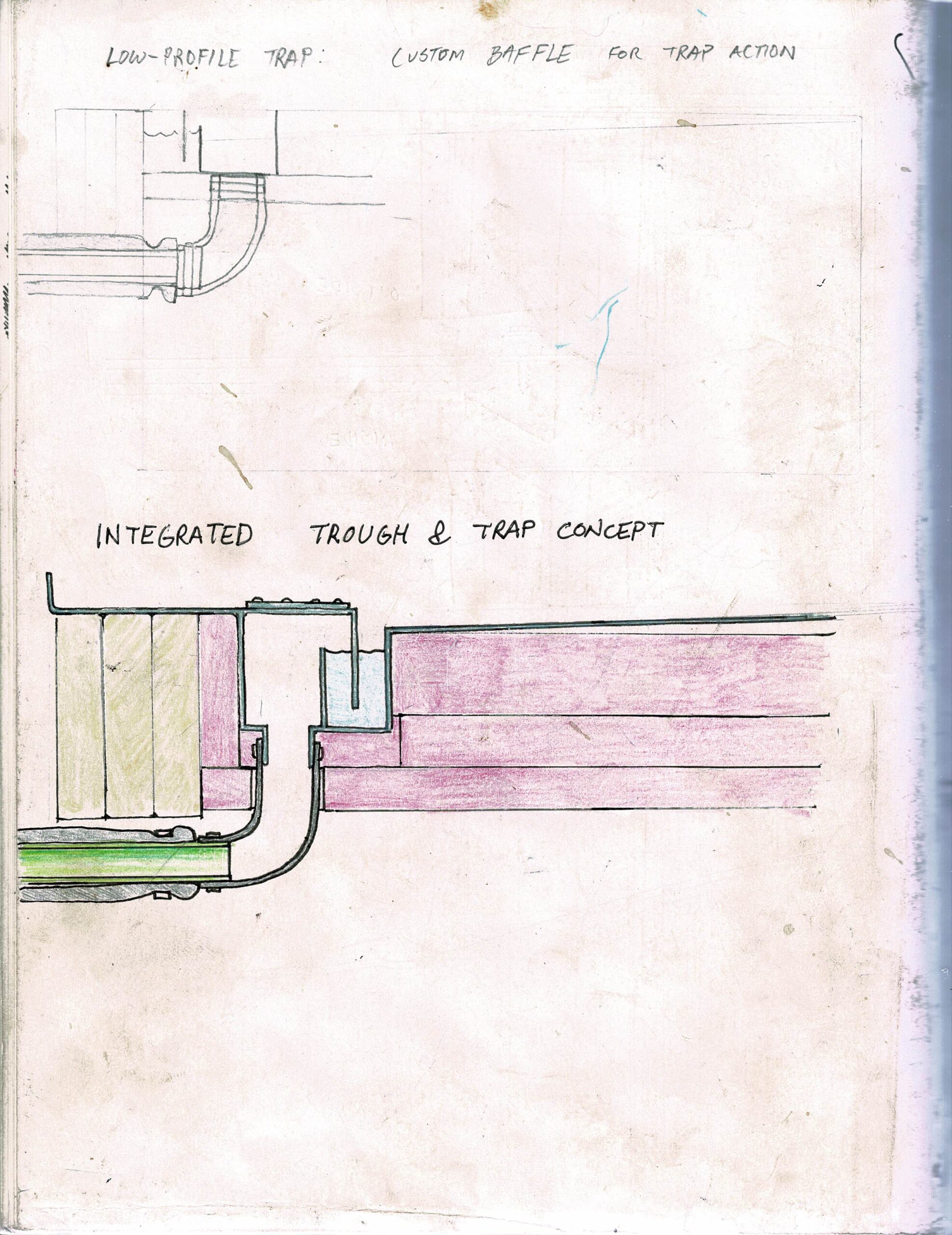
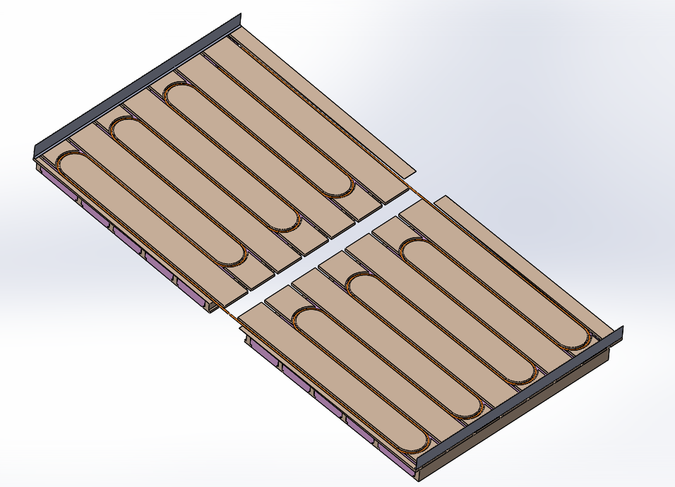
With floor longevity in mind, I decided to incorporate radiant heat into the design of the floor assembly. I grew up on a commercial dairy and working and repairing the milking parlor made me keenly aware of just how challenging it is to keep a wash-down environment from rotting away. As shown in Figure 18 and discussed in the results section, a radiant heat loop and air-space channels vented to the wall cavities and eventually back to the interior will hopefully provide a drying effect to the floors and walls to improve the longevity of the system. While every attempt is being made to keep water inside the interior envelope, a provision for water ingress must be made.
Cladding Prototype
The final physical build component completed during the SARE research window was a prototype of the ModAPS wall cladding assembly. As previously mentioned, the role of the cladding is primarily to act as a weather barrier and to provide supplemental conduction insulation. After planing all boards to 1.13" (34.3 mm), I used my shop's single-spindle shaper to cut the tongue and groove profiles for the sheathing. Like other efforts in this prototype phase, the time required to complete the operations were not viable. However, it is very common for small sawmill operations to have single-pass commercial moulders that would be able to quickly produce the tongue and groove sheathing boards for such an application.
MMP-Specific System Design Phase
In September of 2022, I made the decision to halt prototype fabrication activity and focus solely on producing a finished design to share in this report. The test builds of the previously discussed sub-assemblies went very well, and there were no fundamental changes that precluded using those designs in the composition of an application-specific Modular Meat Plant (MMP). This phase of the project ended up being a very steep climb as many sub-components within the facility required detailed design. This approach has been met with appropriate criticism: The world is full of skylights, doors, squeeze chutes - many of the same sub-components that I found myself designing. However, a significant motivation for this project is to give myself and others the independence to construct needed technology or hire others to do so. There's an important difference between choosing to order a door that meets a certain need and having no choice but to order the same door. In a future of uncertain supply chains and manufacturing consolidation I need the freedom to decide if I make or buy. It is an over-simplification to say that the design of the MMP is "finished", but I am committed to it for the the first build at Haystack Farmstead. It is discussed in detail in the attached summary report.
Observations of Small On-Farm Slaughterhouses 2012-2022
To help inform my design process, I occasionally shadowed at a small USDA-Inspected slaughterhouse in Southern VT that performed inspected slaughter and cut and wrap of cattle, goats, sheep and poultry. My observations are as follows:
- Conventional squeeze chutes are not ideal for stunning operations - Dr. Temple Grandin's website recommends a traveling head-restraint that allows the head restraint to come to the animal rather than requiring plant operators to coax the animal forward to the head-gate. I witnessed several stressful and time-consuming episodes of cattle balking at the head-gate. My observations and Dr. Grandin's recommendations informed my design of a manual head-restraint that travels to the animal.
- Movement of blood-water should be automatic - This really goes without saying, but the facility I worked at had a blood pit that was manually pumped out into compost totes. It was an example of poor design hampering productivity. It was frustrating to facility workers and wasted labor expense.
- Hide Pullers Should be Used - The facility I shadowed at did not have a hide puller and the negative impact on productivity greatly outweighs the upfront cost of installing one. Without at hide puller, plant operators must skin the entire animal and it's a waste of time. With a hide puller, operators need only skin enough hide off of the rear legs to provide enough skin to complete the chain lash. My proposed MMP design features a hide puller that utilizes the facility's main hoist
- Wash-down Equipment is as Important as Value-Adding Equipment - Provisions need to be made to ensure wash-down operations are efficient. A booster pump should be employed to deliver higher water pressure and flow and the facility's hot water delivery should be sized to match. If water supply is inadequate, clean-up operations for the facility simply take too long.
Please see the ModAPS_MMP_2022_Report brochure attached to this project for a detailed discussion of the final proposed design for the MMP build.
I of course hoped to be done with the MMP at this point and successfully operating a vertically integrated livestock business. That has not happened. But the modeling and build methods developed over the last year during this project's "reboot" show incredible promise. I hoped to have more cost analysis data to share with other farmers interested in building small facilities, but the reality is that my system is still very much in the creation phase. I apply as much engineering and experiential know-how into the formulation of physical designs and approaches, but that's the best I can do at this point. I can't say how much the facility I'm building will cost yet. However, when you look at how this facility is being made - with replication central to its mission, it's not a stretch to say that future cost-analysis will be very accurate and helpful for reviewers. If the design does end up being replicated, perhaps revisions needed will be minor enough that less focus will be needed on creative design and the analysis and optimization process can begin. Perhaps the design and build of the MMP will be close enough to the mark that design changes will be driven by cost analysis! I genuinely hope this proposed design has enough good design in it that it's not a "crumple and toss" case.
Education & outreach activities and participation summary
Participation summary:
Outreach regarding this project will become more relevant once the MMP is complete and can be used for demonstration purposes. At that time, actual productivity data will be available, along with total project materials costs etc. that will be valuable to livestock producers interested in similar scale processing. Until then, focus will remain on developing and constructing the MMP.
See the Modular Meat Plant Development Report under Information Products
Learning Outcomes
The most significant and unexpected result of this research and development project has been the synergy between modular building and locally generated wood products. As mentioned, the initial proposed modular construction method featured the use of shipping containers. I converted 2 individual 20'(6.1m) containers into components of the on-farm slaughterhouse. One of which was an Office/Bath unit that will be used in the final installation of the facility. After constructing early prototypes of the ModAPS units using wood construction, I would not return to building with shipping containers. As demonstrated in the attached pdf report, there is so much more flexibility when configuring modular buildings using wood frame construction. Performing modifications to shipping containers is loud, and often times releases toxic fumes that are difficult to manage. It's not impossible to work with containers, but the more you ask a shipping container to be anything other than a shipping container, the less economical the method becomes.
Building modular with wood offers the advantage of a blank canvas for space creation. With shipping containers you have a floor, 3 walls, a ceiling and two heavy doors regardless of whether they are needed. When creating a square work-area from two containers, you have to start by removing and reinforcing the walls of the containers. That is to say, you have to spend money going backwards before you can move forward.
The link between the sawmill and the farm is so strong. There was quite literally nothing wasted from our exercise milling on-farm to construct the modular units. From the roughly 7000 board-ft of lumber produced from our purchased truck and pup load of hemlock, we produced nearly the same volume in slab-wood and nearly 30 cu. yd. of sawdust. The sawdust was brought right into the barn for cattle bedding, and the slabwood was used to heat the wood kiln and the house via the outdoor boiler.
As a means of curtailing particulate emissions and sequestering carbon, it would be fascinating to evaluate a bio-char generator and syn-gas generator working in concert with an on-farm or near-farm sawmill. If the slab-wood makes the power for the sawmill, the bio-char goes in the soil and the milled lumber is used to build a small value adding facility that pulls another commuter off of the road, the entire system starts to have major carbon implications.
Project Outcomes
The most important outcome of this project is the catalog of modular building components that I have developed and the use of multi-configuration modeling to allow diverse design outcomes. As I demonstrate in the attached summary report, this catalog of build elements can readily configure different production workspaces. Over time, as I improve this design catalog, I will be able to easily configure facilities to match any small production need. I will also be able to rapidly release high quality blueprints that enable efficient construction of said facilities. As mentioned several times in the report, research activity through this SARE Farmer Grant has enabled me to create a living breathing system, not just a few renderings of limited applicability. There is still a long way to go, but I am so pleased to have produced such a valuable, tangible outcome from this research.
I'm most pleased with the decision to pursue wood-frame construction, drawing inspiration from the modularity and ruggedness of shipping containers rather than getting mired in the tricky aspects of building with them. I also learned to put the spatial requirements of the facility first and then task the modular building system to be flexible enough to accommodate those needs. Designing something from scratch is very hard. You have nearly infinite options and within each of those, endless possibilities. You have to use your best judgement, weigh factors, make assumptions, calculate loads and stresses, then throw a dart at the wall and commit. What's further challenging is that all subsequent dart throws are impacted by the early ones. It's very common to get a good ways in and say "this is junk". That's happened a few times to me, but in this last wave of work, in developing the L2W scheme and the rugged frame components, I, along with the contractors making the parts, have been genuinely pleased with the assembly outcomes.
When you agonize over creative design choices, design maturity and assembly repetition come as such a genuine refreshment. Going forward, the plan is to complete the MMP using the methods shared in this report. We will build dozens of laminated timbers and brackets, several drained floors, doors, windows and skylights. Those repetitions will feel good, because we will start to reap the rewards of so-much up-front design effort.
Future work depends on how well the system performs and whether subsequent project cost reviews and future cost analysis of the construction methods demonstrate promise. If so, there will be overlapping development and promotional activity. This system is not a proposed cure-all for the small farmer. In order for distributed on-farm production to work, the products generated from such facilities must go into sound markets. That is another steep hill to climb and so future systems-level collaborations will certainly be in order.