Final report for FW15-057
Project Information
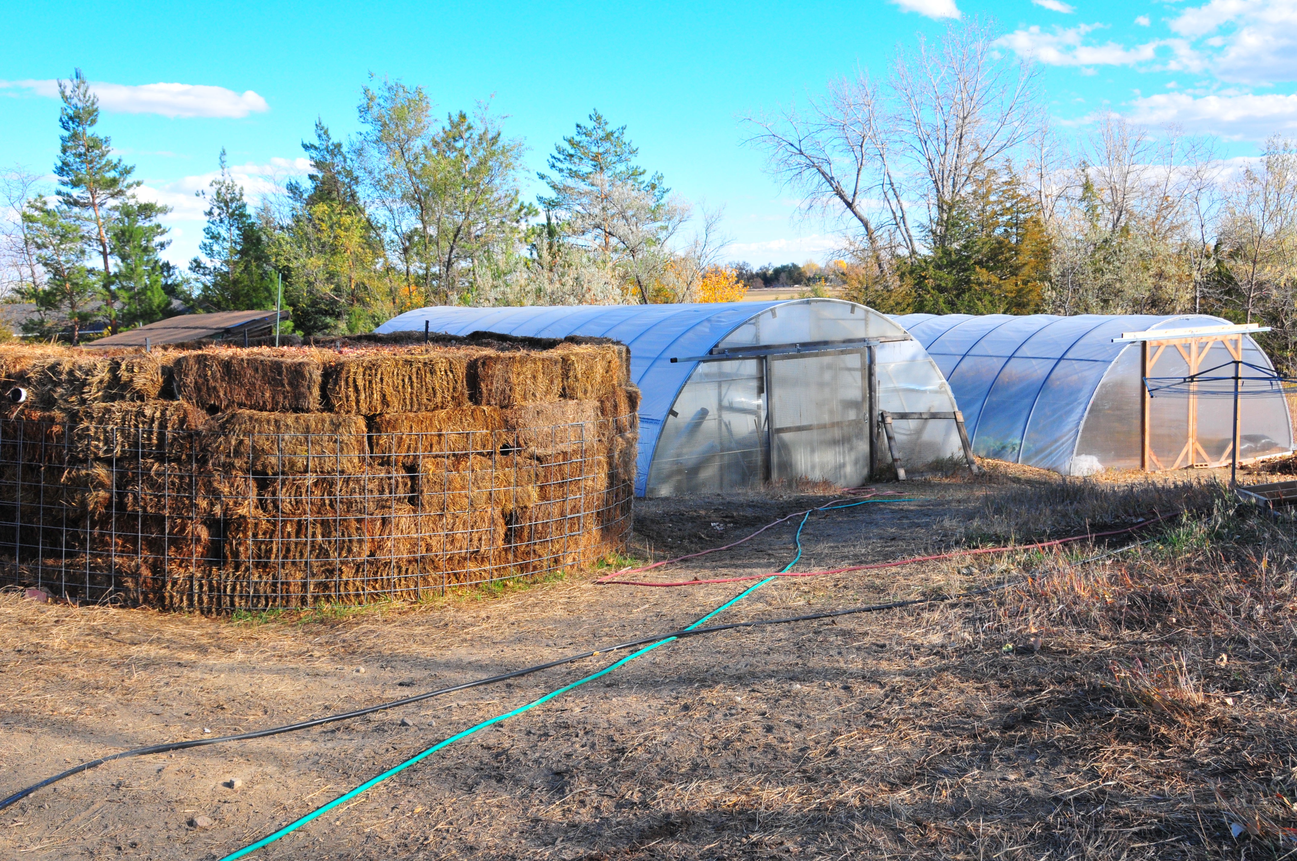
At Sunspot Urban Farm, we built two large compost heaters (2015 and 2016) for conveying heat to a nearby high tunnel via a hydronic system. The compost heater built in 2015 failed to maintain heat but the compost heater built in 2016 maintained adequate temperatures from October 2016 to February 2017. The hydronic system connected to the 2016 compost heater failed to deliver enough heat to raise soil temperatures in the high tunnel. In 2017, to further understand heat transfer to soil, we enlisted the help of an engineer consultant to help us develop and evaluate a small-scale compost heater system to heat the soil in a small greenhouse; this smaller system conveyed heat to the soil but again not sufficiently to consistently raise soil temperatures. In 2018, we professionally analyzed the compost generated from the compost heaters built in 2015 and 2016. Compost analysis results indicated the creation of a high quality finished compost. For educational and outreach purposes we have discussed this project on farm tours associated with Colorado State University, Front Range Community College, and other organizations and posted all annual reports (2015-2018) associated with this project at our farm's website http://sunspoturbanfarm.squarespace.com/research/. Feedback from tour participants emphasized their support for sustainable farm practices.
1. Build a compost heater and hydronic system for delivery of compost-heated water to a high tunnel to increase soil temperatures. 2. Monitor and evaluate the heat delivery of the compost heater to warm the soil in a high tunnel during winter and spring months. 3. Evaluate the quality of the compost for growing crops. 4. Disseminate information about the project.
Cooperators
- (Researcher)
Research
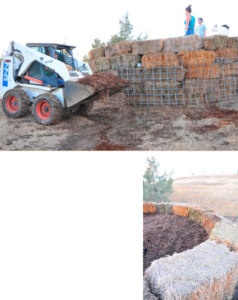
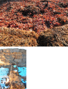
We built our first compost heater on October 11, 2015. Its dimensions were 13’ diameter and 7’ high. These dimensions included the insulating wall and roof of hay bales (75 total bales). Internal to the insulating layer is the pile proper, consisting of a mix of hardwood chips (60%), horse manure (30%), and wood shavings (10%). During construction, ditch water was pumped onto the pile to fully moisten all materials. We assembled materials from various local sources: 80 cubic yards of hardwood chips, 24 cubic yards horse manure, 15 cubic yards of wood shavings, 1200’ of ¾” irrigation tubing, hard wire mesh used for concrete foundations, cattle panels, 4” diameter perforated tubing, 4” diameter pipe, zip ties, ShurFlo pump. In constructing the pile, we were assisted by ten people, one of whom operated a Bobcat front end loader to haul materials. Completed pile was approximately 34.41 cubic yards. This pile failed to deliver heat so on October 13, 2016, we met with our technical advisor Addy Elliott of Colorado State University, to examine the failed 2015 pile and to discuss an improved design for the 2016 pile. We agreed to these design changes: larger pile; better mixed and wetted materials; and methods for injecting air and water deeply into the pile periodically after construction (see Table 1).
Table 1. Attribute comparison of 2015 and 2016 compost water heaters. In contrast to the 2015 heater which failed to provide continued heat, the 2016 pile has maintained high temperatures for several months.
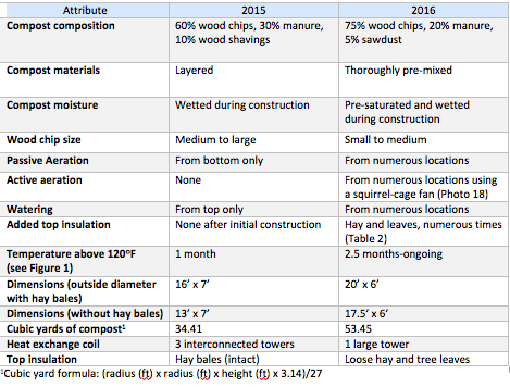
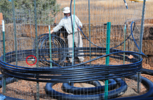
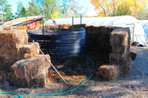
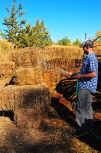
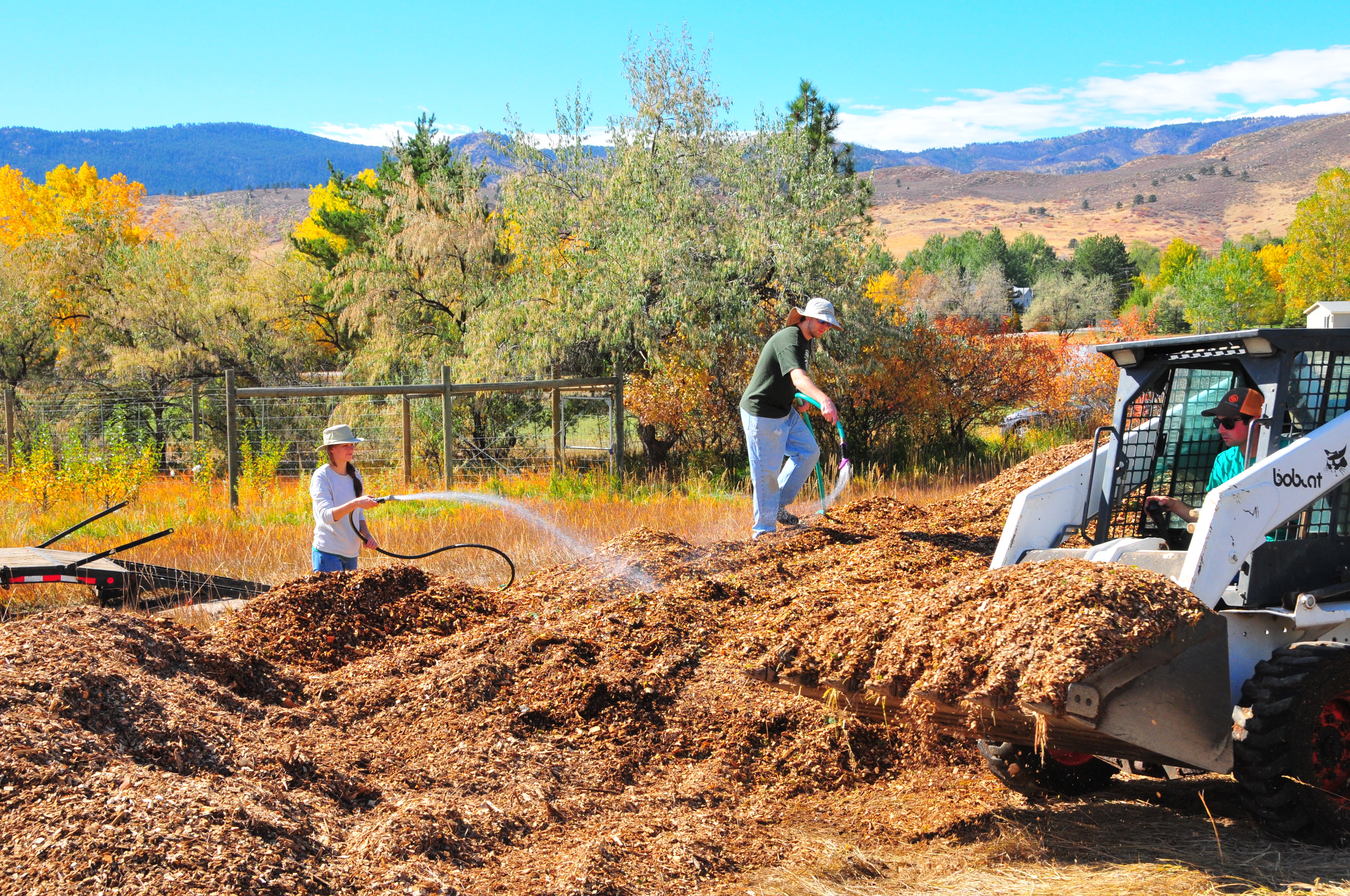
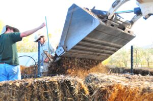
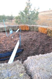
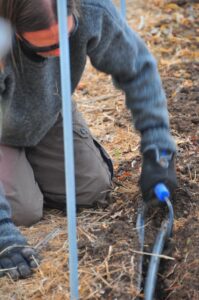
We built the new heater on October 15, 2016 (see Photos 1-30 below), incorporating the new design features (Table 1). The pile’s dimensions are 20’ diameter and 6’ high, including the wall of insulating hay bales. Internal to the insulating layer, the pile is 17.5’ diameter. The pile consists of a mix of hardwood chips (75%), horse manure (20%), and sawdust (5%) (Photo 11). These three materials were mixed thoroughly by a skid steer immediately prior to construction of the pile. During this mixing, the materials were thoroughly wetted for four hours, using two garden hoses (Photos 9-10). This process of thoroughly mixing and wetting the materials, which was not performed in the building of the first pile in 2015, is thought by us to be the primary cause of the sustained heat of the 2016 compost heater.
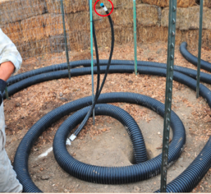
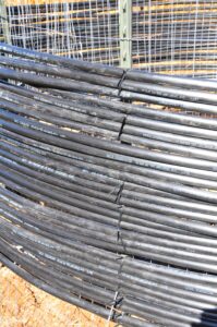
Prior to adding the mix of decomposable materials, a single central coil-tower of ¾” polyethylene tubing was wrapped around a 5’ high column of wire fencing held in place by 8 T-posts (4-posts of 8’ and 4 posts of 6’ pounded into the ground); the fencing was securely wired to the T-posts (Photos 4-8). The coil-tower is 8.5’ diameter. The ¾” tubing was purchased in 100’ rolls (much easier to manipulate than the 300’ rolls used in the 2015 pile).
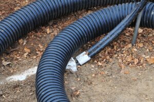
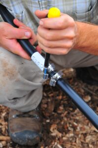
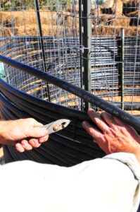
Eleven rolls were used, for 1,100’ of tubing for the coil-tower. Individual rolls were interconnected by grey, straight plastic barbed irrigation connectors secured by screw-style hose clamps (Photo 5). The tubing was secured to the fencing by 12” zip-ties (Photo 6). The tubing coil begins 18” above ground, for two reasons: a 100’ perforated, flexible plastic 4” diameter tube was laid in a coil at the base of the pile for passive aeration of the pile; and a foundation of decomposable mix would eventually be poured at the base of the coil-tower for warming the water-filled tubing (Photo 4). Four feet of ¾” polyethylene tubing contains 2 cups of water; therefore, the coil-tower holds 34.375 gallons of water.
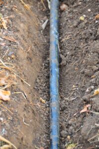
The tubing of this closed system coil is linked to the high tunnel through an underground triplewall pipe containing two lines of tubing (Photos 2 and 3): the line entering the pile (the “cold” line) enters at the base of the coil and spirals to the top; as it ascends, it becomes the “hot” line. Once the “hot” line is at the top of the coil, it runs down through the center of the heat exchange coil to exit the pile via the triplewall pipe. The triplewall pipe consists of a 4” diameter hard, plastic tube; the tube is 10’ long, and 2 tubes were used. The “hot” and “cold” lines run conterminously in the tubing, and each line is insulated with a 1” thick foam sleeve. The tube containing the lines is buried in an 18” trench, filled with dirt, and covered with the original dirt plus a line of hay bales (Photo 20 insert). A note on this step: It is important to clearly label the “hot” and “cold” lines (depicted in Photo 5) and to feed them into the tubing prior to building the coil, doing so only after completing these three steps: duct-taping each line closed, duct-taping the lines together to unify them, and duct-taping the ends of the foam sleeve to the lines so the sleeve will not peel off when the unified lines are forced through the triplewall pipe.
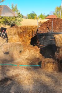
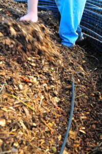
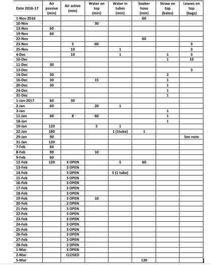
Prior to adding the mix of decomposable materials, a hay bale wall was built to outline what would become the circumference of the pile (Photos 4, 8, and 13), initially 3 bales high (ultimately 5 bales high). Into the space created by the hay bale wall, a skid steer successively dumped the pre-mixed and pre-wetted materials, first filling within the coil-tower and then around the coil-tower (Photos 12 and 13). Three people spread and compacted the compost material as it was dumped. As the materials were piled higher, 2 soaker hoses (a 200’ and a 100’ hose) were wound around and within the heat exchange coil (Photos 14 and 15), and six 10’ perforated triplewall pipes (hard, plastic 4” diameter tubes with 2 rows each of 10 holes; Photo 16); these pipes were added roughly equidistantly throughout the pile. Each of these tubes terminates at the hay bale wall for allowing the adding of water or air (Photo 17 and 18); each tube has a removable cap. At 3’ above the ground a second perforated, flexible 4” diameter tube (identical to the one on the ground beneath the coil-tower) was placed, with one end terminating at the hay bale wall, for aeration. As the pile reached the desired height of 6’, more tiers of hay bales were added. Once 6’ was reached, the pile was capped with 18” of tree leaves and loose hay (Photo 20). Note: After construction, the pile has continually settled, so many additional leaves and hay have been added to maintain the top of the pile at the level of the top tier of hay bales. All post-construction adjustments of air (passive and active; Photo 18), water, and insulation to the pile are listed in Table 2.
To monitor the success of the pile, we measured its temperature repeatedly, beginning day one. We inserted three compost thermometers of 3’ to 4’ long at these strategic locations: the center (4’), along the heat exchange coil (3’), and at the edge of the pile (3’). When inserting the probes, we were careful not to puncture the polyethylene tubing or soaker hoses; for future piles, we recommend deciding during construction where the probe thermometers will be placed to insure no punctures.
Photos (1-30) of 2016 Compost Heater Construction
Results and Discussion
Compost Heater and Hydronic System
Temperature readings of the 2016 compost heater spiked initially to 170°F and the heater maintained temperatures in the targeted range from October 2016- February 2017 before dropping (Figure 1; closed circles).
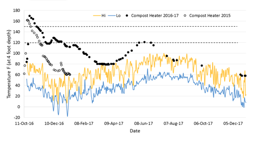
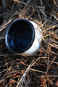
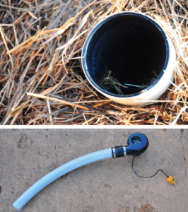
Wet aeration vents indicated moisture in the pile for many months in 2017 (Photo 32). When an aeration tube was dry we used that as an indicator to add water to the pile from above or by putting a hose down the 10 foot pipe. We stop adding water to the pile as soon as the water began flowing out the bottom of the compost heater. Our repeated attempts to amend conditions in the pile ultimately failed (listed inTable 2). However, after 5.15 inches of rain in April-May 2017, the pile temperatures climbed back into the targeted range (see Figure 1) for a brief period before falling out of range.
Table 2. Air, water, and insulation amendments to the 2016-17 compost water heater. We maintained a manipulation period between November 1, 2016 through March 18, 2017 with the intent to keep the pile within targeted range. Aeration to the compost was both active (fan) and passive (removal of caps from aeration triplewall pipes), quantified as total minutes (min) per each aeration tube. These amendment attempts ultimately failed to keep the pile within targeted range. Water was added to the pile until it ran out the bottom of the compost heater.
Hydronic System: Conveying Heat to a High Tunnel Bed and Soil Temperatures
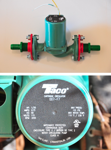
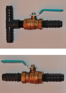
The temperature of water flowing through the irrigation tubing is measured indirectly via the strap-on thermometers described in the previous section; the measurement is “indirect” because they are attached to the outside of the tubing and do not contact the water (Photo 26). These three measurements are regularly taken and recorded. Using the 1/30 horsepower pump, the “cold” return line frequently had readings near freezing (32°F), although the “hot” line regularly ran above 100°F, indicating that in the 40’ garden bed the tubing dissipated about 70°F. To discover how quickly the heat dissipated, we took additional temperatures on December 16, 2016.
Three measurements were taken on the “cold” return line in the garden bed. These measurements occurred at the east end, midway, and just prior to exiting the bed (to return to the compost heater). The measurements were taken by removing the soil from above the line in those three locations, strapping on a strap-on thermometer, waiting several minutes for the reading to stabilize, and then recording the number. The readings were 58°F (east end), 59°F (midway), and 58°F (west end). The “cold” line outside the bed, however, was 40°F, meaning that nearly a 20°F reduction occurred immediately upon leaving the garden bed. A likely explanation is that this section of the “cold” return line is permanently exposed to the ambient temperatures and thus does not receive the insulating effect of the surrounding soil; thus, an insulator of some kind is needed for the “cold” return line prior to its reentering the buried triplewall tube. On this same day, in contrast to the buried polyethylene tube temperatures of 58°F (midway), adjacent soil temperatures midway on this date averaged 42.5°F. Thus, although hot water is circulating in the hydronic system it has yet to ameliorate adjacent soil temperatures.
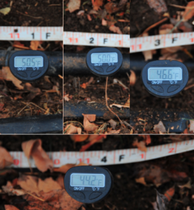
The temperatures of the “hot” supply line immediately entering the high tunnel varied by pump power. With the 1/30 horsepower pump, these measurements were generally around 50°F. Meanwhile, the readings just downstream of the pump were generally close to 100°F, indicating that the pump itself was warming the water. Because of these results, we replaced the small pump with a 1/8 horsepower pump, to move the water more quickly through the system. With this larger pump, the “hot” line entering the high tunnel was warmer, near 80°F; the temperatures just downstream of the pump tended to be similar, indicating that the 1/8 horsepower pump’s heat is having less of a heating effect. After 2 days with the 1/8 HP circulating pump, we measured the soil temperature at four points where the “hot” supply line first entered the bed, in a series of 1’, 2’, 3’, and 4’ from the start of the bed. The results indicate that the heating system had an effect, but the effect diminished quickly. The results from the “hot” line (80°F when first entering the bed) were soil temperatures of 50.5°F at 1’, 50°F at 2’, 46.4°F at 3’, and 44.2°F at 4’ (shown in Photo 30). Given that plants require a soil temperature of at least 50°F to access soil nutrients, these preliminary measurements indicate either of two conclusions: the hydronic system is insufficient to warm the bed; or, the system needs more time to transfer the heat from the polyethylene tubing to the surrounding soil.
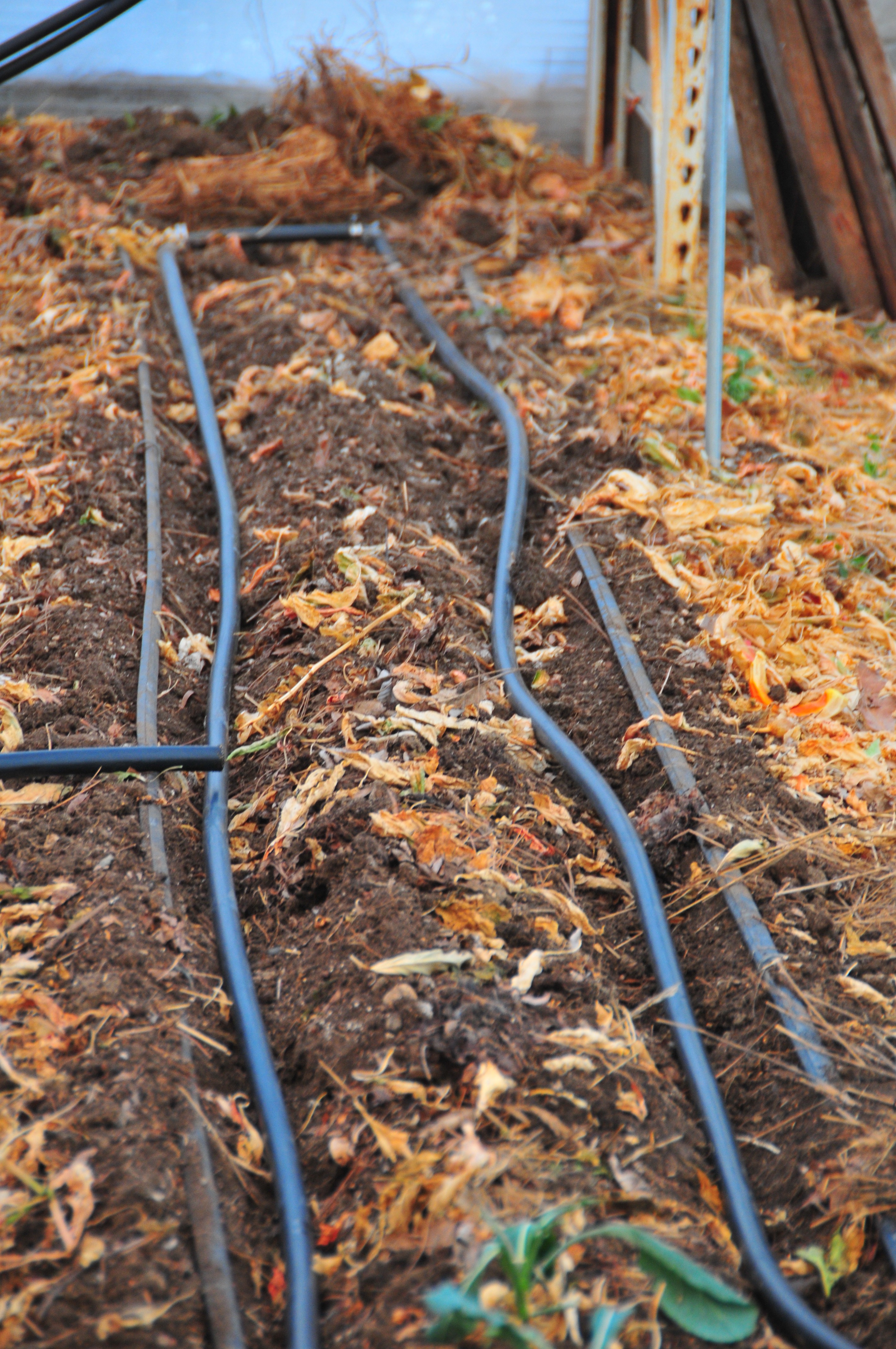
In early 2017, the buried ¾“ irrigation tubing running the length of a 40’ bed (treatment bed) had no measurable effect on the overall soil temperature, when compared to the adjacent 40’ control bed that contains no such hot water tubing. We measured the soil temperature over 27 days (December 10, 2016 through 31 January 2017) along the hydronic system and in an adjacent control bed without hydronic tubing. Two temperature readings (12” apart at depth of 4”) were taken in the middle of each treatment and control beds (Photo 33). Soil temperatures ranged from 37-50°F and 35-51°F in treatment and control beds, respectively. Average temperature for the treatment bed (43.3°F) was identical to that of the control bed (43.3°F), indicating that the hydronic delivery system was not transferring and ameliorating soil temperatures as designed. The hot water delivery temperature entering the bed during this time period averaged 98°F (range: 80-119 °F). After shutting down the pump in February and March these same beds again had similar temperatures over a 23-day period with an average of 55.6°F and 56.1°F, for treatment and control, respectively.
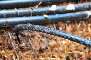
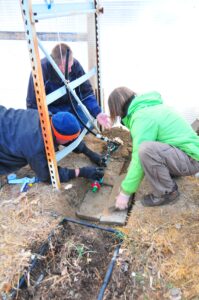
We attempted to understand why the 2016 system was not working by digging into the top of the compost heater with an engineer consultant (Larry Maple) to check tubing and aeration vents (Photos 34-36). We found a kink in the water tubing (Photo 37) that might have greatly reduced water flow in the hot line and impaired functionality of the pump. The tubing of the heat exchange coil maintained its shape well (Photo 38). Our excavation of the top proportion of the pile revealed a very wet top layer with large dry pockets of wood chips below (Photo 39). We also discovered aeration tubes that were severely bent due to weight of the compost material (Photo 40).
Given the failure of the 2016 compost heater and the failure of the previous compost heater of 2015, we resolved to develop an alternative test for a hydronic system and enlist the assistance of an engineer consultant, Larry Maple. We would build a compost heater that is smaller, cheaper, and easier to manipulate than the two wood chip piles of 2015 and 2016; and we would connect it to a smaller greenhouse, anticipating that a smaller hydronic system will be easier to measure and to troubleshoot. The details of this effort are described below.
Small Scale Hydronic System Test with An Alternative Pile Construction (2017)
We constructed a small compost heater pile of coffee grounds and connected it to a small greenhouse of 12’ by 6’. We did this for two reasons. First, due to various problems with the two wood chip piles of 2015 and 2016, we were not able to successfully test the hydronic system’s ability to heat soil, and a small pile seemed suitable for such a test. Second, given the high expense of building a large wood chip pile and our failure to aerate and water it sufficiently over the months, we built a small pile without wood chips to seek an inexpensive and manageable way to maintain high heat in a compost heater.
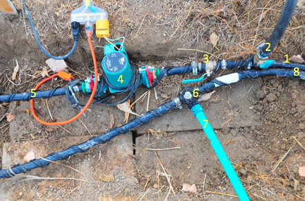
This small pile was circular, 9’ in diameter and 4’ in height. It was composed of coffee grounds (50%), yard waste (40%), and soil (10%) (Photo 11). In the center was 100’ of ¾” polyethylene irrigation tubing, wound in a coil and positioned from near the top of the pile to the bottom, where it exited and traveled 15’ to the greenhouse (Photo 12). The tubing to the greenhouse ran underground, covered in foam sleeves, and buried under a foot of soil. Once inside the greenhouse, the tubing was arranged in a long rectangle with L-joints at each corner to allow the tubing to run the length of the greenhouse and then return to its origin. This rectangle consisted of 25’ of tubing and was buried in the soil 8” (Photo 13). The goal was to continuously transfer the heated water from the compost pile into the greenhouse soil and measure the soil temperature. To conduct the water through the system, we used a pump (4008 SHURflo; Photos 14-15). We measured the temperature of the pile with a 19” compost thermometer. We measured the temperature of the hydronic system using strap-on thermometers and thermowells.
Our goals for the coffee ground compost heater were to answer two questions: (1) Can a hydronic system attached to a compost heater raise soil temperatures? (2) Can coffee grounds serve as a material for the compost heater, in replacement of wood chips?
Results for small scale heater (2017)
Question (1): We did not find evidence that a hydronic system heated by a compost heater can significantly raise soil temperatures. While the heat from the pile was successfully transferred into the greenhouse, the heat through the hydronic system did not remain hot enough for long enough to make a significant difference to soil temperatures, although there was evidence of some warming.
The transient nature of the heat from the system became evident immediately upon engaging the system. We could directly sense the effect of the hydronic system during the initial minutes of running the system. Within seconds of turning on the pump, the exposed tubing in the greenhouse would flex and slowly move as warm water from the pile pushed the cool water through the system. By a hand gripping the exposed tubing, we could sense the sudden warmth and could follow it through the feet of exposed tubing until it emptied into the 5-gallon bucket that served as a reservoir in the greenhouse. Indeed, the cool water in the bucket would gradually warm as this process continued. The hydronic system was working. But the system could not maintain significant heat, as will be described below.
After a couple of minutes of operation, the inflow of water from the pile would cool to the touch and would remain cool for as long as the pump remained running. The only way to again have warm water running through the system was to turn off the pump for hours. After the delay and the pump was restarted, the pattern would repeat: a few minutes of warm water flowing through the system (detected unmistakably by watching the tubing flex and move, and by feeling the warming of the tubing and feeling the water emptying into the 5-gallon bucket reservoir), followed by steady coolness. This pattern is very likely caused by the insufficiency of the pile to heat the coil rapidly enough to sustain the conveyance of warm water to the greenhouse. A larger pile with hundreds more feet of tubing in the coil might remedy this problem—although an increase in the length of this tubing in the pile would require an equal increase in the amount of tubing in the greenhouse, according to our engineering consultant, Larry Maple; on the other hand, a slower pump might remedy this problem—yet when we attempted to slow down the pump by engaging a constrictor valve that we had built into the hydronic system, the pump began to heat up rapidly, convincing us to reopen the constrictor valve. The failure of the system to consistently bring warm water into the greenhouse was not solved by us.
Nonetheless, we were able to document temperature changes in the water during operation of the system. When the pile was consistently around 130°F, the water temperature in the greenhouse tubing would be around 90°F. On April 25, the coil in the pile was 132°F, the water entering the soil in the greenhouse was 93.7°F and exited the soil at 93.3°F (measured by thermowells). As the water left the greenhouse, passing through the pump just before exiting the greenhouse to journey underground back to the pile, the temperature was 94.6°F (thermowell measurement). The slight increase in warmth after passing through the pump is likely attributable to the pump’s own heat. These temperatures in the 90s presumably transferred some heat to the soil, although the difference in entry and exit temperatures was negligible, suggesting almost no heat transfer. The soil temperatures at this time were 61°F at the east end of the bed and 58°F at the west end, measured by 3” probe thermometers, in the evening at 5:00. Interestingly, one hour later, the thermowells showed 2.5°F increases in water temperature, indicating that the pile was transferring more heat as the evening wore on. Nonetheless, the soil temperatures did not change; this is possibly explained by the greater sensitivity of the thermowells compared to the 3” probe thermometers used in the soil.
During that night of April 25, the greenhouse low was 37.2°F, but the outside low was 32.5°F (and there was frost on outdoor plants and house roofs the next morning). This temperature difference suggests that the hydronic system and the heat of the pump were moderating the air temperature of the small greenhouse. How much of this effect was due to the hydronic system itself and how much was due to the heat emanating from the pump, we do not know.
The next morning, April 26, the coil temperature at the base of the pile had fallen 20F over the night. Also, the thermowells showed decreased temperatures of the water going in and out of the soil of almost exactly 20°F. At 5:50pm April 25, the temperatures were 96.3°F (into soil), 95.9°F (from soil), and 95.4°F (exiting greenhouse). At 8:30am April 26, the readings were 76.3°F, 75.9°F, and 76.5°F.
After leaving the pump off for 8 hours during the daylight hours of April 26, the pump was turned on again at 4:20pm. Consistent with the pattern already discussed, the tubing responded to the sudden influx of warm water and then cooled. Despite cooling, the temperatures at the entry and exit points of the soil showed higher temperatures than were recorded earlier that morning after the pump had operated all night long. The 4:20 temperatures were 86°F (into soil), 85.7°F (out of soil), and 85.7°F (exiting greenhouse), approximately 10°F higher than the morning readings. The soil temperatures were 64°F at both the east and west ends of the bed.
The next morning April 27 at 7:30am, the temperatures were about 10°F cooler: 74.8°F (into soil), 74.2°F (out of soil), and 74.9°F (exiting greenhouse). These numbers were similar to those of the previous morning, while outside temperature was near freezing. At noon, with the pump still running, all temperatures had increased about 2.5°F, presumably due to heating by sunlight.
During the nights of April 27, 28, and 29, the pump ran. The morning temperatures of the next days confirmed a pattern detected in the readings of April 25, 26, and 27: temperatures were approximately 30°F cooler than the temperature of the coil in the pile. As the pile cooled across the days (because its heat was transferred to the greenhouse), the temperatures declined proportionally, staying about 30°F below the coil temperature. Hence, assuming this pattern is generalizable to other future compost heaters, maintaining a compost heater of 130°F or higher will provide at least 100°F water for one’s greenhouse.
While our data are consistent with this claim of a 30°F differential, it is not obvious where the 30°F are lost. A likely explanation is that 30 degrees are lost as the water moves underground from the pile to the greenhouse. Yet if this were true, one would expect that a similar loss of temperature would occur when the water moves underground from the greenhouse back to the pile. But our data show no temperature loss in that movement. The differences in reading from exiting the greenhouse to entering the pile were less than a degree for six days (April 25-30). We have no data showing a difference of more than one degree. Perhaps, because the lines underground share one underground trench (and despite foam insulation), the hot line from the pile is cooled by the cold line coming from the greenhouse (resulting in a 30°F loss), and the cold line is warmed by the hot line (causing the cold line to not lose warmth).
The warming of the soil by the hydronic system was confounded by the warming of the soil by the sun. To offset this effect, we measured temperatures of the soil in five gradations, each 1” apart: at the buried tubing, and at 1” and 2” to the south, and at 1” and 2” to the north of the tubing. We used a 3” probe soil thermometer. We conducted these measurements on April 26, 27, and 29. The data show that on two of the three occasions the temperature was hottest at the tubing and least hot two inches away, in both directions. These data are consistent with the claim that the flowing of warm water through the tubing was warming the soil. However, the differences between the hottest and coolest locations were typically less than 2 degrees; and on one date, the five temperatures were nearly all the same. It is also interesting to note that while the temperature differences were slight for any given date, the three sets of data (from each of the three dates) differed widely from each other. The hottest locations for each date were 68.9°F (April 26 at 5:15pm), 63.5°F (April 27 at 7:30am), and 55.2°F (April 29 at 8:30am). This wide disparity may be explained by the heat of the day, but part of the explanation may be the effects of the hydronic system, for the system was hotter on April 26 (mi-80s) than April 27 (mid-70s), which was hotter than April 29 (mid-60s). We did not measure soil temperature in a control plot near the rectangle of buried tubing; we should have done so in order to address the question of how significantly the hydronic system had increased soil temperatures relative to surrounding soil and the effects of solar energy.
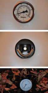
One complication we experienced was measuring temperatures using strap-on thermometers. After starting the system the evening of March 29 and letting it run all night, we discovered the next morning that the strap-on thermometers were unreliable. They differed widely in their readings: 78°F, 82°F, and 100°F, although they were located near each other on the same tubing (Photo 46). Given that the temperature at the base of the compost pile at that time was 89°F, the third reading had to be erroneous, so we stopped using that thermometer. Of the other two, only one responded reasonably to the influx of heated water whenever the system was first turned on, so the second thermometer was also retired. These thermometers could not be calibrated despite our efforts and our consultation with the manufacturer. We recommend using a thermometer that can be calibrated easily and that can maintain the calibration for months or using thermowells. After discovering the flaw in the strap-op thermometers, we inserted thermowells for directly measuring the water temperatures, and they worked well, although they are more awkward to use than a strap-on model; we recommend a strap-on model that can be reliably calibrated, if such are available.
Question (2): Yes, coffee grounds can serve as a material for the compost heater, in replacement of wood chips. The coffee ground pile heated well and was easy to aerate by turning on two occasions, to maintain high temperatures in the pile. The pile was built on March 25 and registered 20F upon completion. The pile heated quickly, reaching 124°F on March 28, and peaked at 150°F on April 8. The temperature at the coil of irrigation tubing was typically many degrees less hot than the hottest spot in the pile; for example, the temperature at the coil on April 8 was 132°F, nearly 20 degrees cooler than the high of 150°F. This discrepancy is probably due to positions of the thermometers: the pile’s high temperature was taken from the top of the pile, and the coil temperature was taken at the base, where the tubing exited and entered the pile.
Soon after the peak of 150°F, we had to open the pile, causing the temperatures to fall. We had to open the pile because the coil of tubing had not been well distributed through the pile upon first construction, and we supposed that this flaw was preventing the hydronic system from reheating when the water re-entered the pile from the greenhouse. To redistribute the coil, the pile remained open for over an hour, significantly cooling it down.
Once rebuilt on April 8, the temperatures climbed during the next week, reaching 135F on April 15. Over a week later, the pile was still high, hitting 132°F on April 25. But then temperatures began falling inexplicably. During the next five days, readings fell precipitously: 112°F, 103°F, 99°F, 97°F, and 92°F. The causes of this sudden decline are likely due to excessive dryness, deficiency of oxygen, lack of sufficient fresh plant material, or a combination of all three.
On May 2, the pile was aerated by turning with a shovel, and the temperatures began climbing again, peaking at 141°F on May 9. Temperatures remained high until falling to 112°F on May 21. The pile was then watered by hand and received significant rainfall. On May 26, the pile was back up to 121°F. It peaked at 122°F on May 28, and then slowly declined through the first half of June. The pile was dismantled on June 16 when the temperature was 111°F.
The behavior of the pile both conformed to and defied expectations. While it heated quickly and was easy to manipulate with aerating and watering, it did not get as hot as other piles have gotten on our farm and did not sustain high temperatures for as long. We think that these surprising results are partially due to dryness, lack of fresh vegetable material, and from repeatedly pulling heat from the pile via the hydronic system. This pile was built in spring when the farm is producing almost no fresh material, so there was little with which to feed the decomposing microbial community. Had we run this experiment in early winter, the pile would have likely attained and maintained hotter temperatures. Indeed, this experimental pile was built from the remains of a pile that had been built in November 2016 of coffee grounds (40%), garden waste (45%), and kitchen waste (15%). Temperatures in fully built winter piles on our farm commonly remain between 120°F and 150°F until early spring.
The November 2016 pile was typical in its temperature profile. It was built on the 6th, reaching 145°F on November 27, remaining in the 150°s through December and reaching 158°F on January 8, as materials continued to be added periodically, along with water and air. The pile was 154°F on February 12, 152°F on March 10. From this pile, we built the compost heater with the coil of tubing as described above, on March 25. We believe that because the compost heater was built from this old pile, the pile was not able to sustain high temperatures across many months. Nonetheless, the experimental coffee ground pile did demonstrate ease of building and ease of manipulating with water and air and did heat up quickly. Thus, in comparison with a wood chip pile (such as those we built in 2015 and 2016), we believe that a coffee ground pile (with portions of yard and kitchen waste) could serve as a reliable and pliant compost heater for small-scale farm needs.
Feedback from a Local Organic Farm
We discussed the compost heater project with the owner-operators of Native Hill Farm in Laporte, CO. It is the largest organic vegetable farm in our area. They rely heavily on high tunnel production. We met in October 2017 to discuss this project. They were not favorably impressed by the expense and effort required to build the heaters. Additionally, the hydronic system in the soil would interfere with cultivation. They have developed a more efficient method for growing during cold seasons, by using floating row cover and passive ventilation of the high tunnels; this works in northern Colorado due to the relatively high frequency of sunny days.
Photos (31-46) of 2016 Compost Heater and 2017 Small Scale Hydronic System
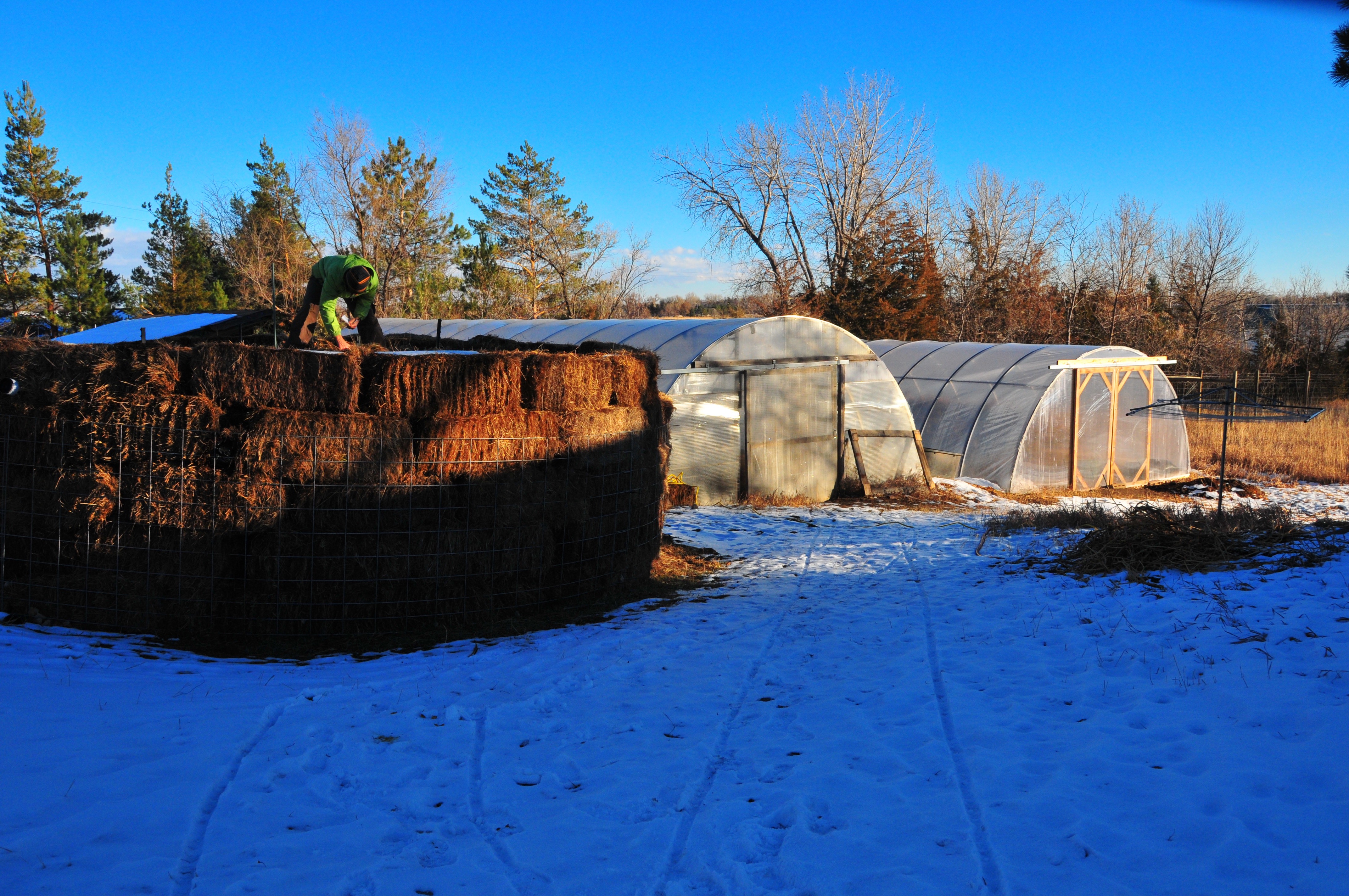
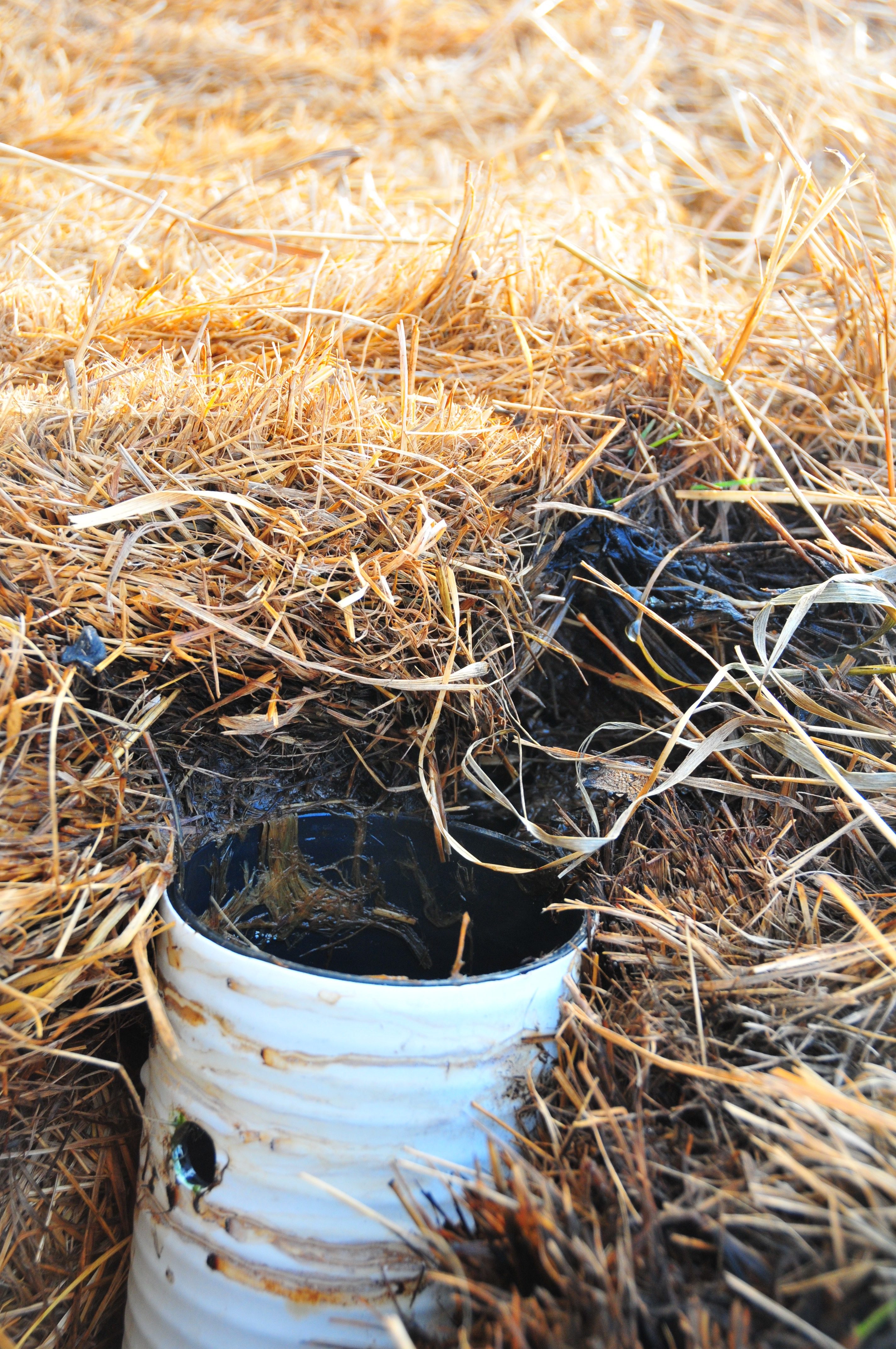
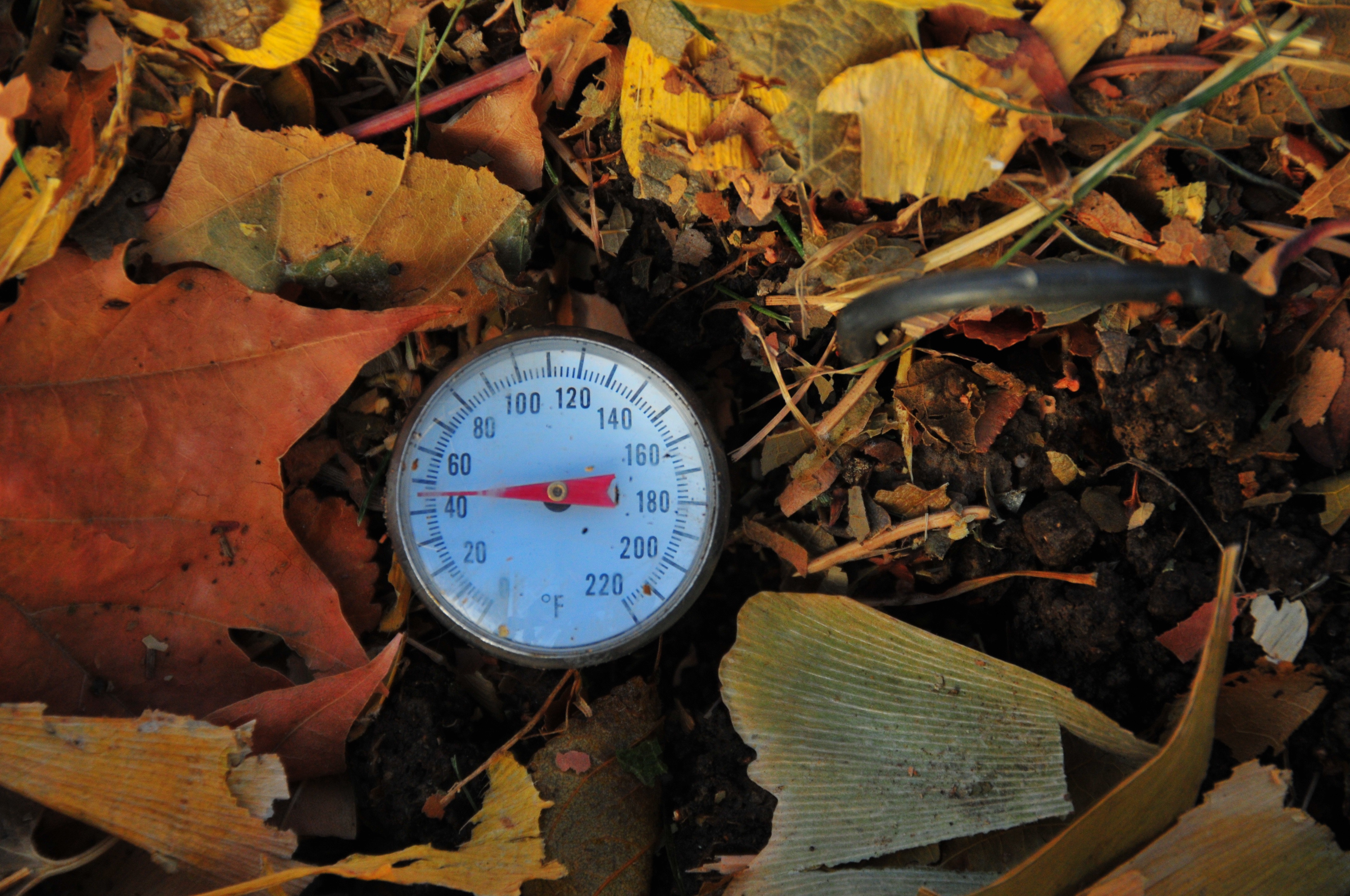
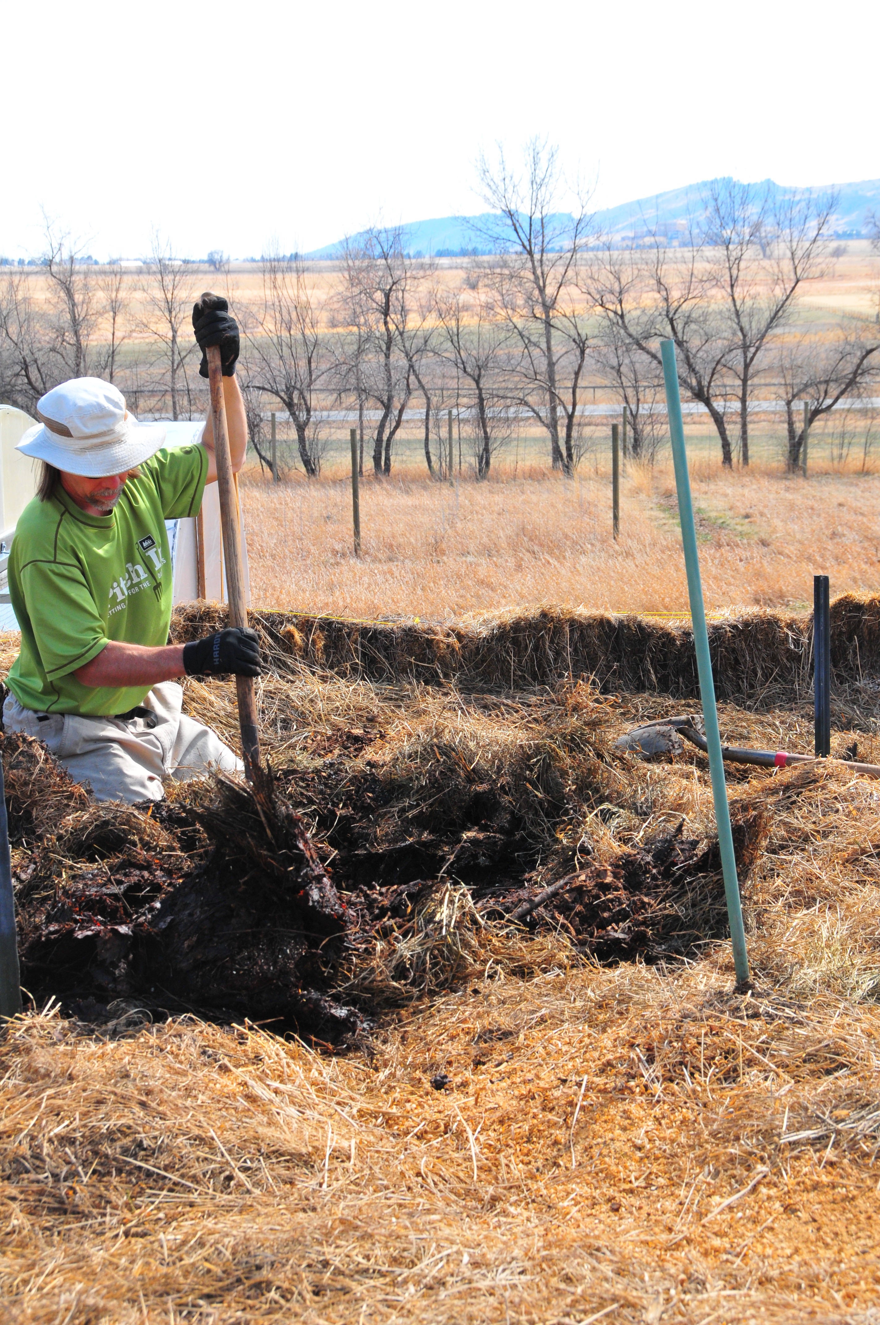
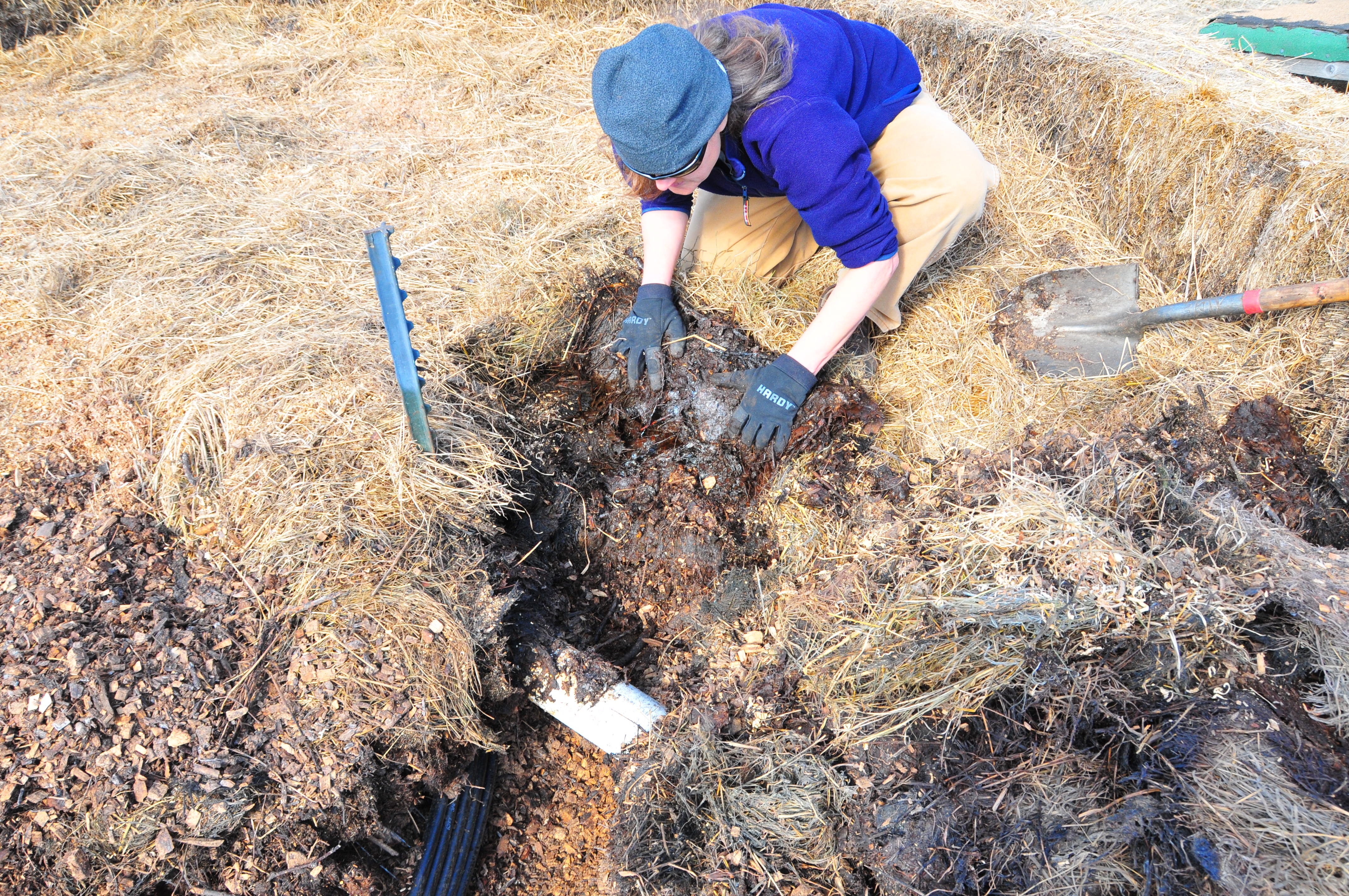
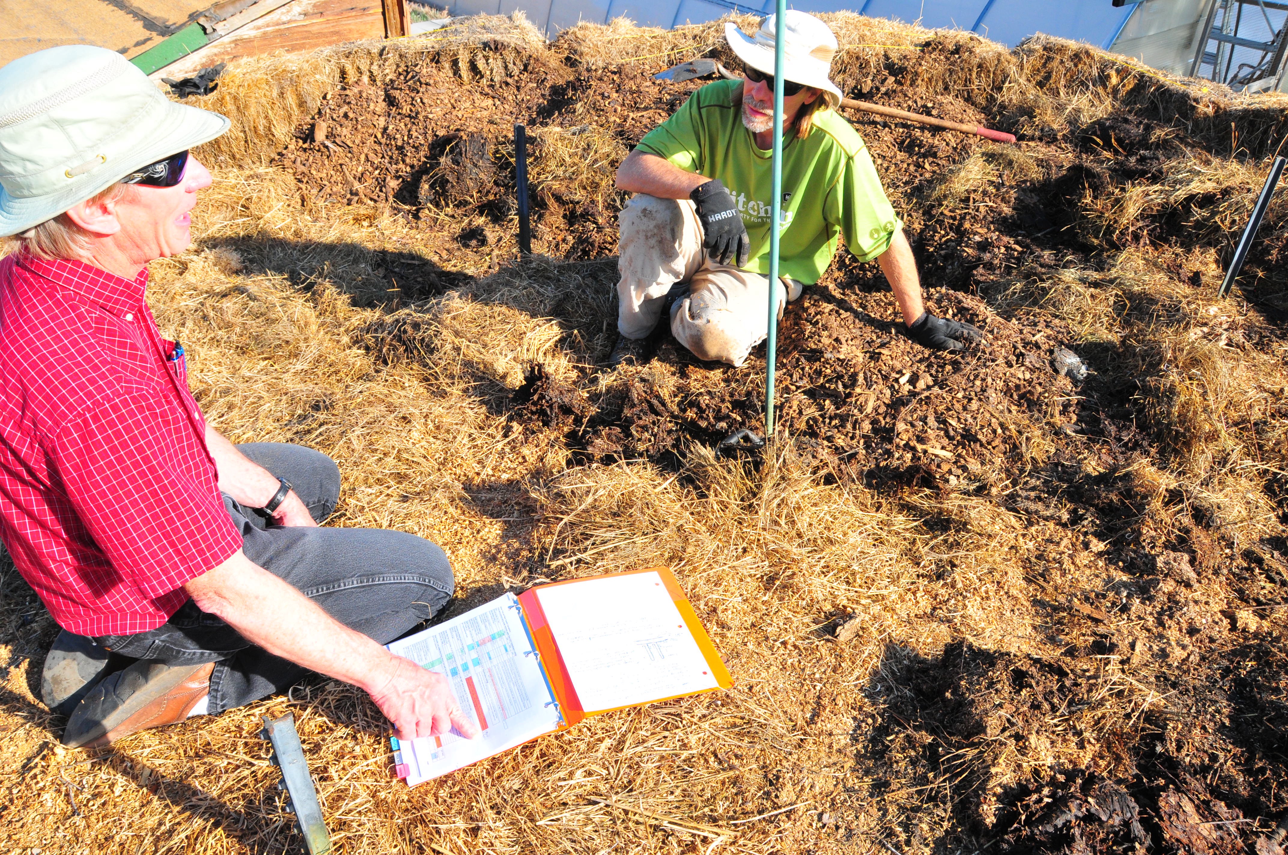
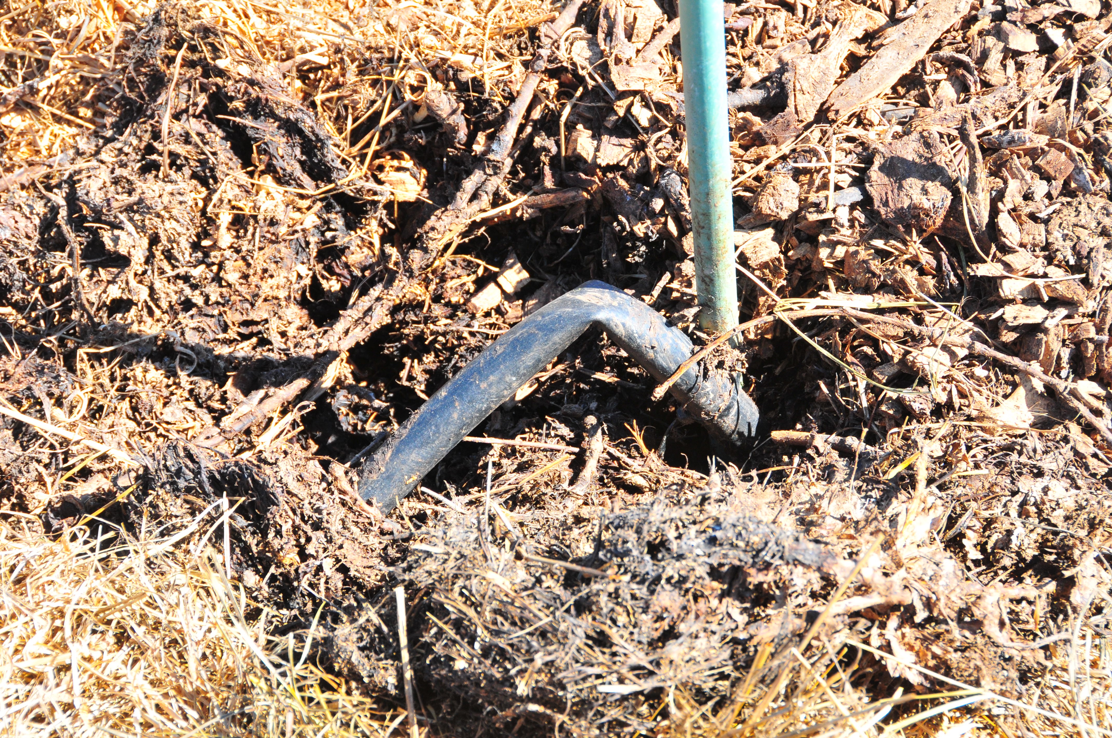
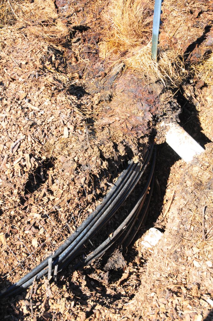
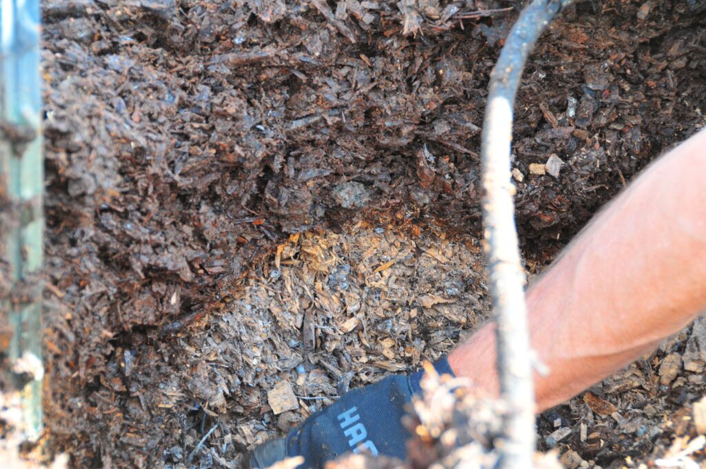
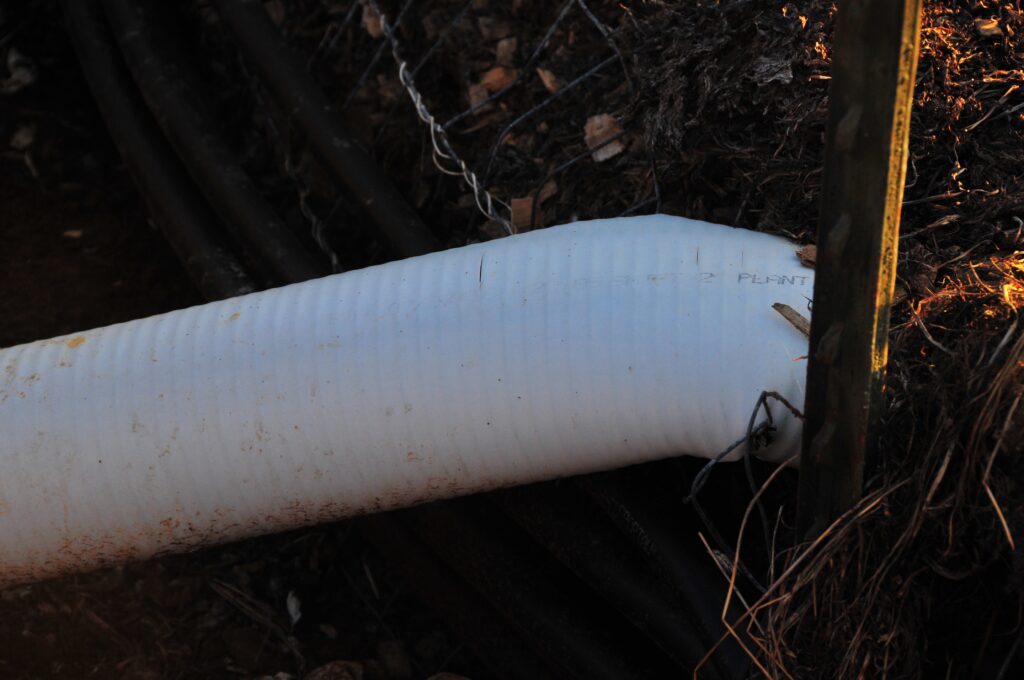
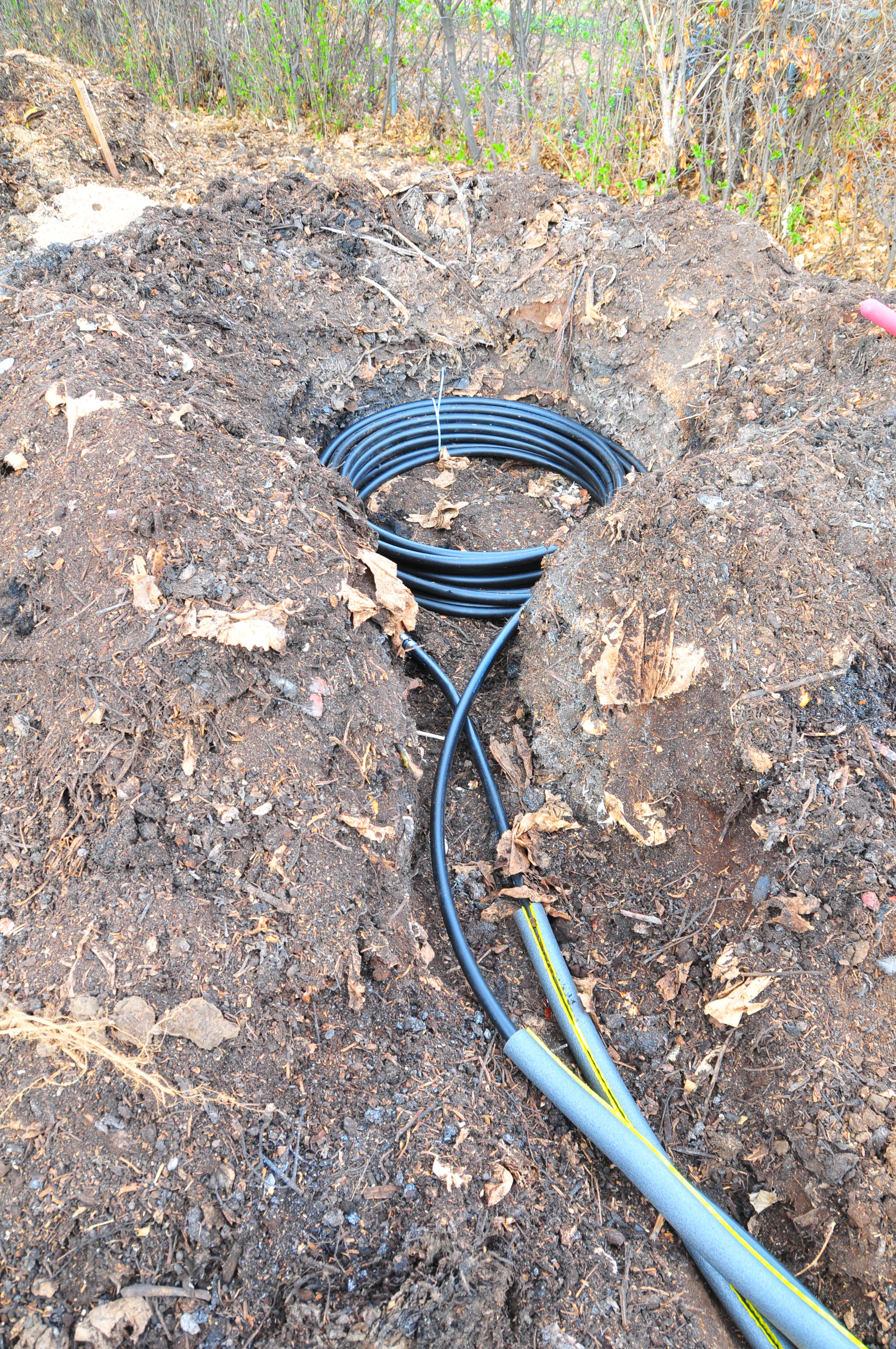
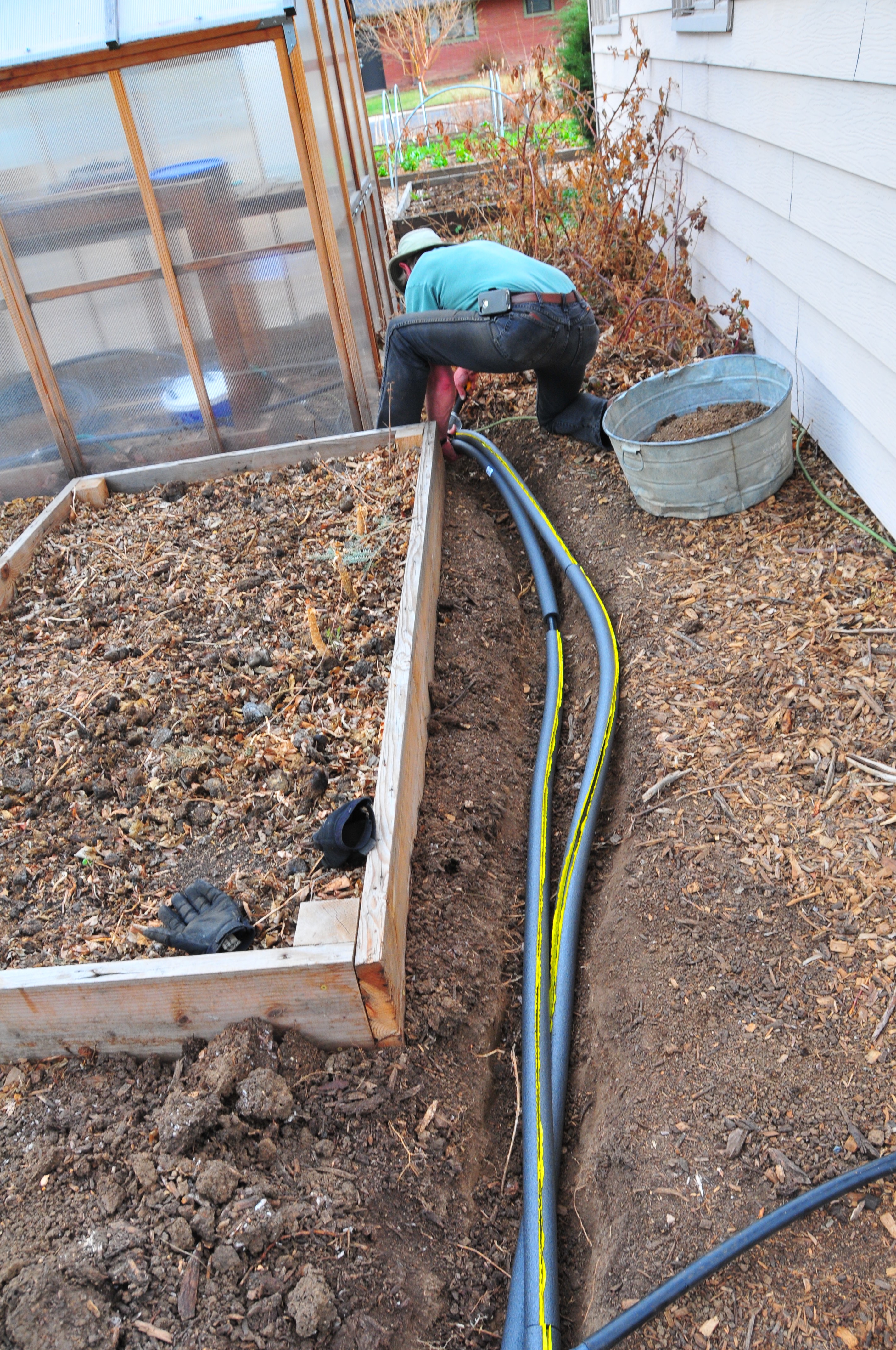
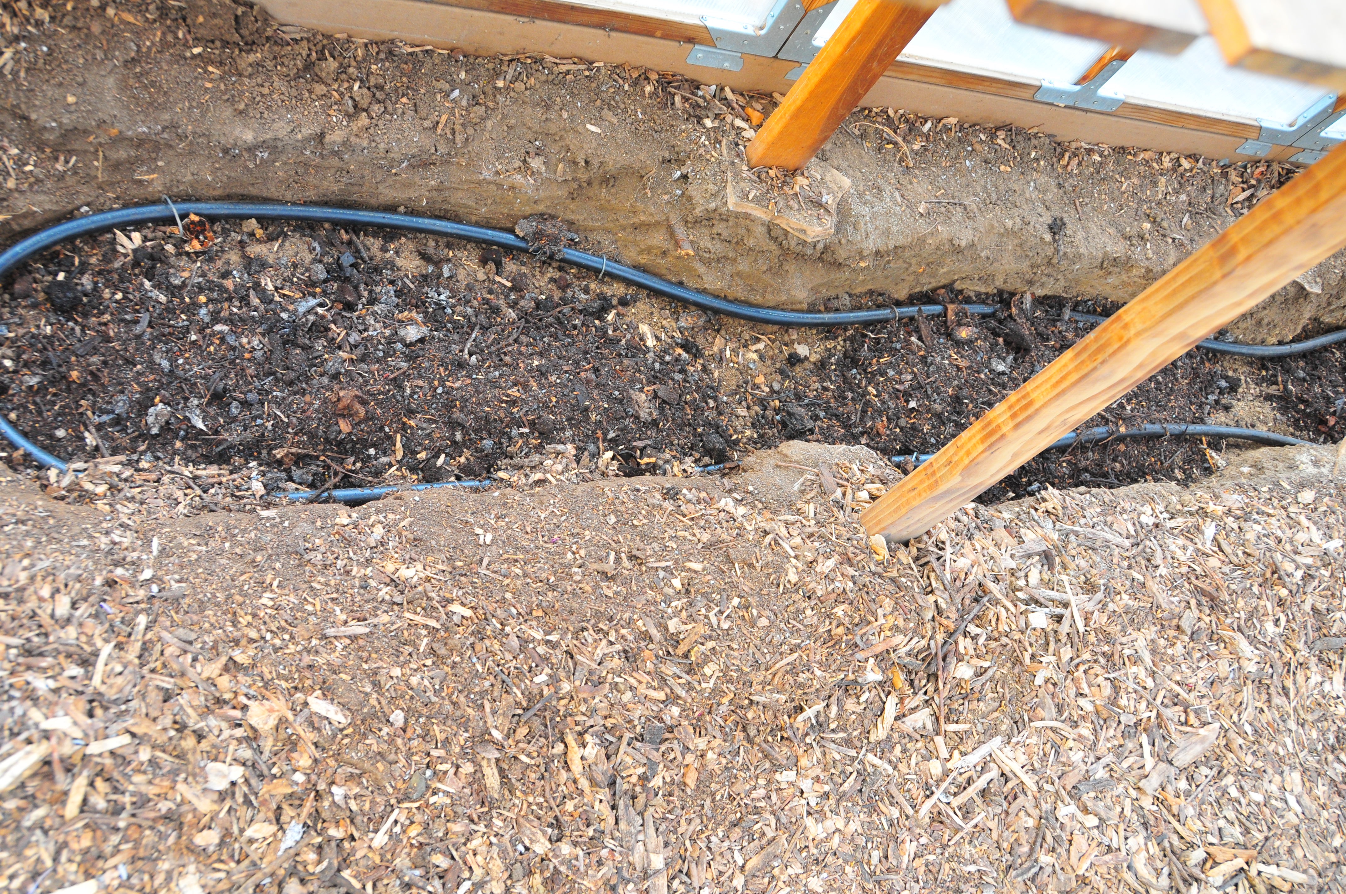
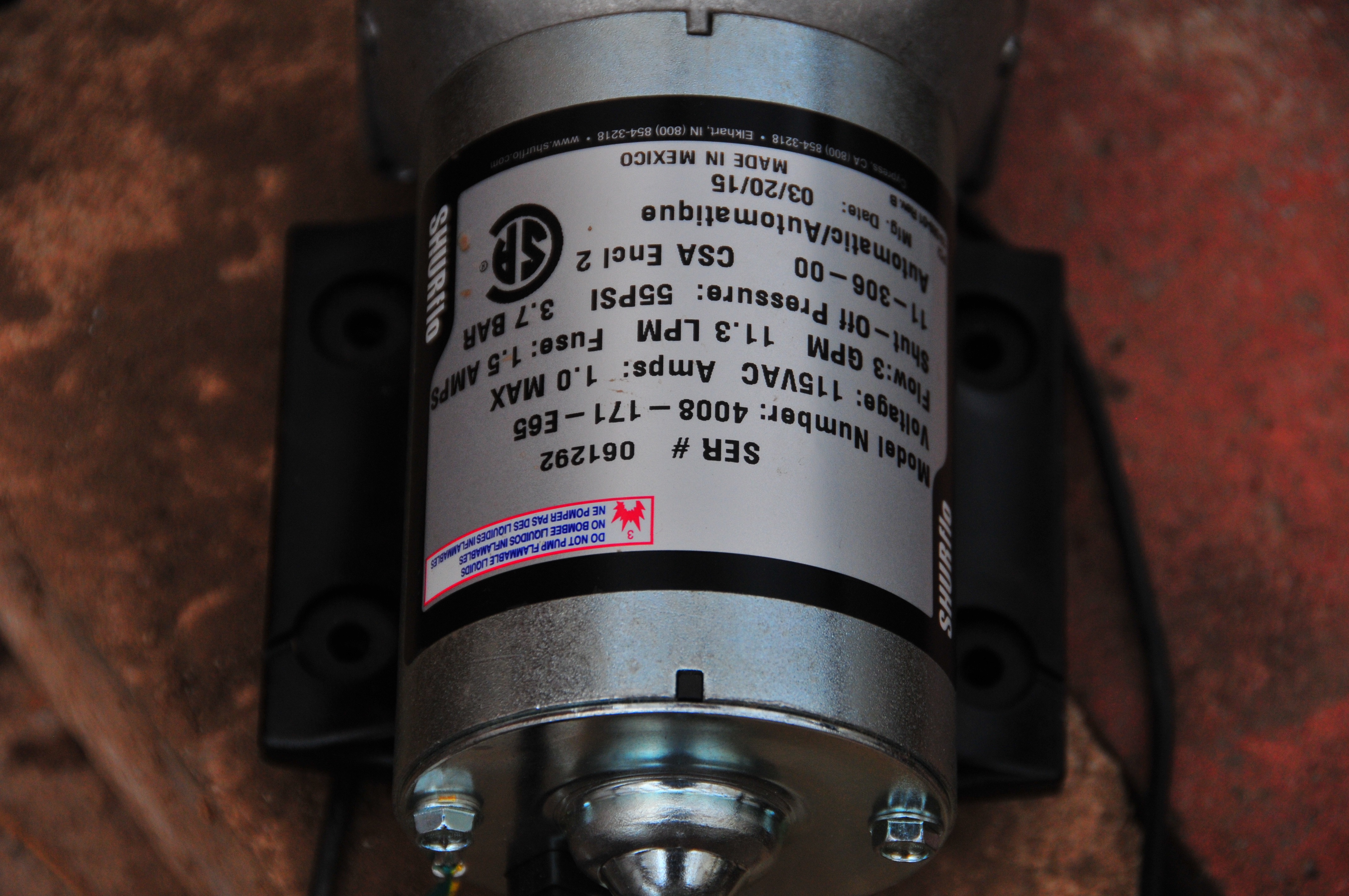
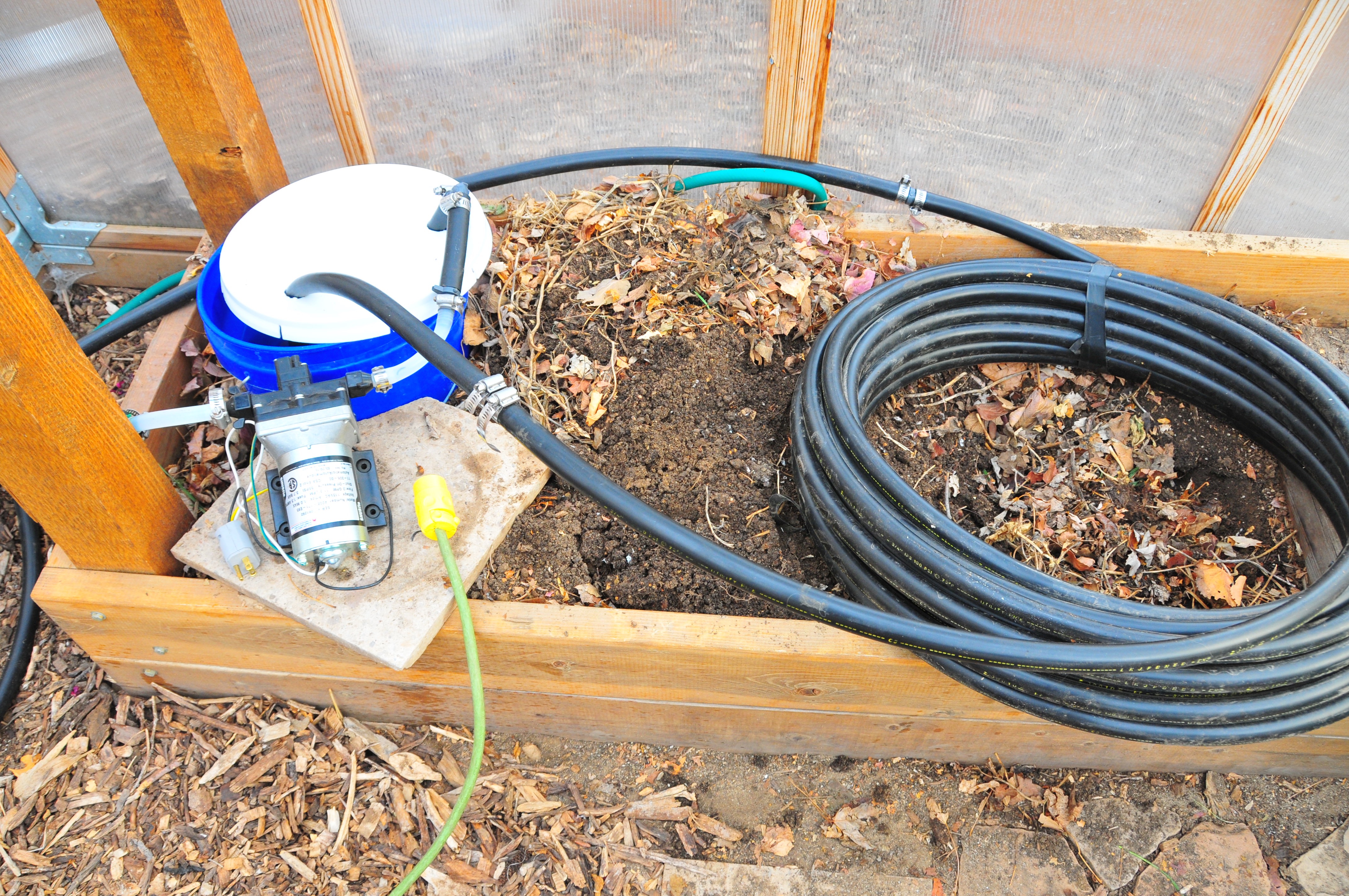
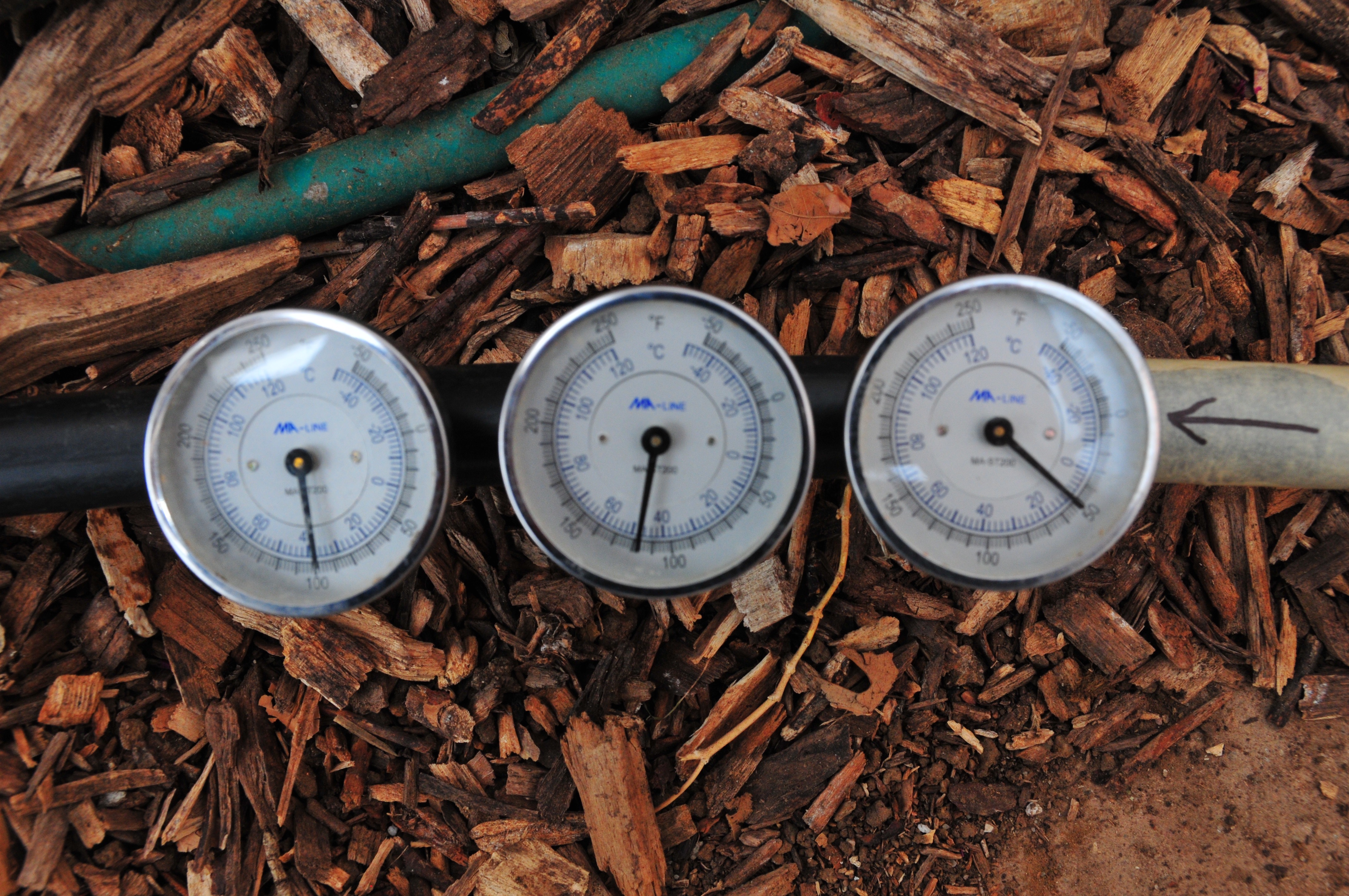 Photo 46. Strap on thermometers produced unreliable readings and were not able to be calibrated. We then switched to using thermowells to obtain direct water temperatures.
2018 Compost Analysis Results
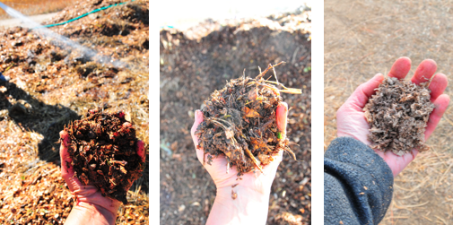
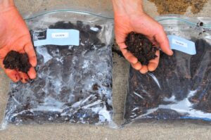
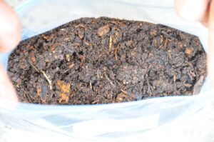
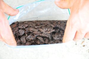
Since construction, both compost heaters remained intact and at their original locations as we allowed them to decompose without turning or active aeration. On June 4, 2018, we extracted 20 subsamples of compost in different locations from each of the two heater mounds, to obtain a representative sample of the material. All samples were obtained 12 inches below the surface of the mound, mixed in a bucket, and then a portion of the mix was packed into labeled gallon Ziploc bags (Figures 47-49), and immediately shipped for analysis.
Compost analysis was conducted at Brookside Laboratories of New Bremen, Ohio (www.blinc.com); in order to expedite analysis, we prearranged with the laboratory the ideal day to send the samples, and we conformed to their recommendation. The lab received the sample on June 7 and submitted results to us on June 11, 2018 (Figure 50).
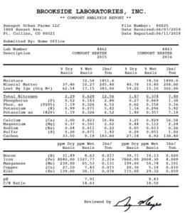
Addy Elliot, a compost specialist at Colorado State University, reviewed the analysis report and provided feedback in July of 2018. Her main comments are summarized below:
The compost was quite mature both years, however more fully composted and stable in Compost Heater 2015 (Figures 47-49). Analysis values provide evidence of adequate oxygen and moisture availability for the composting organisms to flourish and make compost. This was informative as we had been concerned that we did not have adequate moisture in the Compost Heater 2015 because temperatures steadily declined in the initial (and smaller) compost heater. To remedy our concerns, we added more moisture and created a larger compost heater mound in 2016.
Compost Heater 2015 had twice as much nitrogen as Compost Heater 2016, 2.29% versus 1.47%, respectively. Typically, compost averages about 1% nitrogen. Our results are likely due to a higher percentage of horse manure used during Compost Heater 2015 construction. Either way, both compost heaters offer the expected N content.
The salt content of both Compost Heaters was extremely low. This is quite atypical for composts since all added material shrinks/concentrates as the composting process occurs. The high proportion of wood chips and saw dust (our carbon source) relative to small amounts of manure likely explains the low EC value since animal manure is often salty.
The phosphorus and potassium concentrations are as expected for both Compost Heaters. The phosphorus values in Compost Heater 2015 were double the value recorded for Compost Heater 2016, a finding again most likely attributed to the higher proportion of horse manure in that pile. Overall, both Compost Heaters produced high quality compost products that should be safe to utilize on the most sensitive of seedlings.
Finished compost is widely accepted as a valuable soil amendment with many benefits, such as: increased water holding capacity, supplementation of nutrients and minerals, promotion of microbial activity in the topsoil which makes micronutrients available to plants and discourages disease, protection of topsoil from soil erosion, and sequestration of carbon. When Jean Pain’s compost heater mounds stopped producing sufficient heat, he dismantled them and spread the resulting humus on his vegetable beds, with great increase in productivity.
Most organic soil amendments used in Colorado are shipped from afar, with environmental and economic costs to the shipping. We have demonstrated that the decomposed compost heater material is adequate to enrich soils for fruit and vegetable production. While the heaters did not adequately warm the soil in winter high tunnels, the piles did produce a valuable soil amendment. Such piles could be cost effective for farms with large animals and a supply of wood chips brought to the farm by local arborists. With a skid steer, a large pile can be constructed of manure and chips in a day, then insulated with straw bales to be left to sit for multiple years. Piles could be staggered in time to create a continual supply of on-farm compost. Because the internal structure of tubing would not be present in such piles (they are not compost heaters), they would be easier and cheaper to assemble and dismantle than compost heaters.
Acknowledgments
This material is based upon work that is supported by the National Institute of Food and Agriculture, U.S. Department of Agriculture, under award number 140867021 through the Western Sustainable Agriculture Research and Education program under sub-award number [FW15-057]. USDA is an equal opportunity employer and service provider. Any opinions, findings, conclusions, or recommendations expressed in this publication are those of the author(s) and do not necessarily reflect the view of the U.S. Department of Agriculture. We thank Addy Elliot for valuable project input and the following individuals for their volunteer work in constructing the heater: Natasha Varian, Joel Berger, Matt Jones, Leslie Kraynak, Jeff Davis, Mike Knowles, Michelle Haefele, Shauna Leibold, Helen Holmquist-Johnson, Chris Holmquist-Johnson, Page Klug, Todd Paspichal, Garrett Glascott, and Patrick Gazely. Woodchips were sourced from Larimer County tree maintenance and Jordan's Tree Moving & Maintenance, Inc. Horse manure from Brian Fisher, a local rancher. Local artisan wood turner, Steve Germaine, generously provided barrels of sawdust for the project from his beautifully crafted bowls, pots, and vessels (http://www.stevegermainewoodbowls.com). We thank Larry Maple for his numerous volunteer hours, deep thinking, and calculations to help us understand the complexities of trying to heat soil via a hydronic system.
Research outcomes
Education and Outreach
Participation summary:
Education and Outreach 2015-2018
In 2015, one month prior to constructing the first compost heater (2015), we demonstrated the concept of a Compost Heater at an event called The Urban Homestead Tour. We constructed a small compost heater from eight cubic yards of hardwood chips mixed with alpaca manure, surrounding a tower of ¾” irrigation tubing that entered and exited a 12’ x 6’ greenhouse. Approximately 200 people, during the course of the tour, observed the compost heater. Twenty six of these folk signed up to learn more about the pile that would later be built on October 11. Folks on the tour were exposed to 18 education stations with station #6 featuring the compost pile; the following verbiage about the compost heater project was provided:
Anatomy of a Compost Heater to heat the greenhouse. North of the greenhouse are components of a woodchip compost heater. Eight hundred feet of polyethylene tubing filled with water is buried within this compost pile in a closed loop system that can be pumped into the greenhouse during cold weather. We were awarded a 3-year grant with Western SARE (Sustainable Agriculture Research and Educational Grant) to test the feasibility of this practice for heating large greenhouses. At our property west of town, we will attempt to heat our 1,000 square foot greenhouse, using 80 cubic yards of wood chips. A compost heater will obtain temperatures 115-140°F all winter long. If you are interested in this research, please consider signing the email list.
Using the 26 names and emails of tour participants we started a database that indicates an individual’s level of interest in non-mutually exclusive areas (quarterly updates, volunteer, plumbing skills, or assistance with other project needs). All participants wanted a quarterly update, 12 wanted to volunteer, 4 indicated plumbing skills, and 8 indicated that they would be willing to assist with other project needs. Participants were updated via our farm’s website (http://sunspoturbanfarm.squarespace.com/research).
In 2016, we conducted educational outreach in five ways. First, the project was described in three college classrooms at Front Range Community College and Colorado State University. Second, our farm website maintained current reports of this project (https://sunspoturbanfarm.squarespace.com/research). Third, in relation to construction of the system, we educated those persons who helped with construction and who provided us materials and supplies for construction. Fourth, in casual conversations with friends and acquaintances, we have described the system many times. Finally, we are just beginning to dialogue with other growers who are also experimenting with compost water heater systems and synthesized this conversation.
In 2017, we again engaged in educational outreach in several ways. First, the project was described in two college classrooms at Front Range Community College and Colorado State University. Second, our farm website maintained all annual reports of this project (https://sunspoturbanfarm.squarespace.com/research). Third, as in 2015 and 2016, in casual conversations with friends and internet acquaintances curious about the system, we have described the compost heater many times. Finally, we dialogued with other growers (i.e., Native Hill Farm, Laporte, Colorado) about this research and our findings and documented their concerns and reservations.
In February 2018 we worked with Stacie Clary, communication manager, from Western SARE to create a highlight on our research project for the 2017 WSARE Annual Report available at https://www.westernsare.org/Learning-Center/Fact-Sheets/2017-Annual-Report. In October 2018, we conducted outreach in the form of an on-site farm tour and interview that included the compost heater system for two agricultural research associates, Mark Easter and Amy Swan, from Colorado State University interested in writing about our farm's sustainable farm practices. Additionally, we discussed the system during two general farm tours for two classes at Colorado State University.
Education and Outreach Outcomes
Constructing compost heaters to convey heat to soils in high tunnels during cold periods is ineffective at this scale.
Large amounts of quality compost can readily be generated for on farm use with compost heater materials (woodchips, saw dust, manure, and hay bales [for moisture retention and insulation]) without active aeration.
The use of crop protection covers within passive vented high tunnels is an easy and effect practice for extending the season of certain crops in our sunny location.