Project Overview
Commodities
Practices
- Animal Production: animal protection and health, feed/forage, grazing management, grazing - multispecies, grazing - rotational, manure management, pasture renovation, pasture fertility, rangeland/pasture management
- Education and Training: farmer to farmer
- Natural Resources/Environment: carbon sequestration
- Pest Management: sanitation
- Soil Management: soil microbiology
Summary:
Our small grazing operation has evolved from using movable poly twine with few permanent fences to high tensile 6 strand perimeter, 4 strand lanes, and single strand paddocks. The goal is to be able to manage the largest herd our farm can sustain with minimal inputs and simple daily moves of opening gates and checking water and mineral supplies. We intend to produce top quality beef with an improved sward, minimal weeds, and reduced fly populations.
This new infrastructure saves constant climbing our hills to set and remove temporary fences but adds the regular maintenance of the permanent ones, from repairing tree-fall and deer damage to keeping them clean of vegetation. The first year of our new plan saw 2 miles of these fences installed. By the fall, the fence lines were visible from a mile away from the growth of wild carrot and multi-flora rose under the wire. Since we practice organic principles, the specter of using a weed whacker along these fences seemed to negate any advantage of permanent lines, clearly, moving the fence would make these strips accessible for the beeves to chow down before the weeds could take over.
We also have the issue of clipping the weed seed-heads in the rest of the fields, and reducing fly populations by breaking up cow pies before fly larvae can hatch.
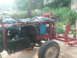
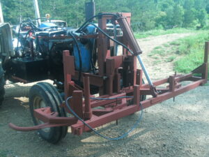
My proposal solved these problems by building a lightweight pasture clipper that has a swing arm to clip under fences. I also am building a towed, trailer-mounted drag, with rollers to drag and roll the fields. This year I used my existing drag to break up the manure and bend over the tillers after clipping.
The clipper attachment required some detailed research and boning up on basic engineering. I started with searching for hydraulic motors and pumps to run off my 70 HP tractor. I settled on some low speed hydraulic motors that would be stepped up with pulleys to get a higher rpm at the cutting head. Higher speed motors were prohibitively expensive. I also had to research the correct rpm for string trimmer line and find out how fast I could make belts and pulleys run. My first few searches and calls steered me away from my initial presumptions and led me to a practical solution.
Hand held trimmers run at about 9,000 rpm. Cast Iron pulleys can go as fast as 6,000 RPM without exploding. The idea of having a pulley explode led me to stay even more conservative. It turns out that feet per minute is a more precise way of describing this safety margin. V belts can travel between 1500 and 6000 feet per minute. Cast iron pulleys can also travel up to 6,000 feet per minute, measured at the rim. Additionally, the speed of the string at its cutting tip is important.
Handheld trimmers have a tip speed of around 25,000 feet per minute. Walk behind units with a 5 hp gas engine for one head have a tip speed of from 18,000-24,000 feet per minute.
V-belts have limitations that need to be addressed. For long life, there is a minimum radius a belt can curve around. My original hope was to use big, thick belts. These require very large, heavy, expensive pulleys. Smaller ones, such as “A” section belts, can handle a 3” or larger diameter pulley at high speed, and when made from Kevlar have a long life. For power transmission, drive pulleys should ideally have 180 degree contact with the belt, and driven pulleys should have nearly120 degrees of contact.
My original plan was to use one hydraulic motor to handle 4, 2-foot-diameter cutters; and another motor on the swing arm to handle one cutter. This would provide an overall cutting width of just under 10', allowing for some overlap between cutters. I staggered the pulleys front and back to prevent the strings hitting each other, allowing for some wear before they needed replacement.
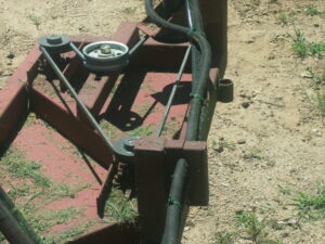
While pricing the belts and pulleys to make this happen it became clear that buying an extra motor was cheaper than all of the pulleys and belts required to connect 4 heads. This created a triangle geometry of one drive pulley with 180 degree contact, two pulleys with over 110 degree contact, and an idler to tighten the belt. Idlers that operate on the back side of the belt need to be at least 4.5 inches in diameter to prolong the life of the belt. Pushing one side of the triangle in towards the center with the idler tightens the belt. This configuration helps get enough zig zag in the belt path to develop the pulley contact required for the belts to operate best.
The hydraulics were very straightforward once the motors were chosen. The only design issue was to decide between series or parallel piping for the motors. The pressure on each motor gets reduced but the gallons per minute stay the same with series. The gallons per minute are reduced but the pressure remains equal for parallel. In my design parallel made sense. A 3/4” hose getting reduced to 3/8” and then sent to two motors did not make sense. By splitting the 3/4” supply with flow dividers, each motor received a third of the pump's output.
Looking online at suppliers I found hydraulic motors that would run on about 4 gallons per minute at 2000 rpm. I found a pto driven pump that puts out 12 gallons per minute at 1500psi. My main flow of 12gpm goes through an open center valve that is connected to a flow divider that splits into a 4 gallon per minute 1/2” port, and an 8 gpm 3/4” port. That in turn is connected to another flow divider that splits into two, 4gpm, 1/2” ports. I learned that these hydraulic motors require a third connection to drain the case of leakage from the main chamber to avoid eventually blowing out the seal. That required finding some very small fittings to connect to 1/4” low pressure tubing for routing back to the reservoir.
The reservoir needs to be at least as large as the pump's gpm, in this case a 15 gallon tank.
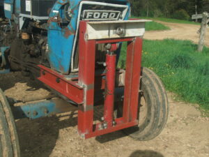
I planned a three point hitch for the front of the tractor that would be raised with a cylinder, and tilted up with another top link cylinder, for cutter head servicing. The valves for these were included with the motor control in a three spool unit.
The final design used 3.35" pulleys above the cutters, and 4.95” pulleys on the motors to step up the hydraulic motor's rpm from 2,000 rpm to 2,955 rpm on the cutter shaft. The tip speed for 24 inch cutting circle is 18,557 feet per minute, right in the low end of the ballpark of other machines.
I was trying to be conservative and may increase the size of the drive pulleys next year to see if the higher rpm works even better. A 6” drive pulley would spin the cutter head at 3,582 rpm and create a tip speed of 22,400 rpm, approaching the high end of existing gas machines. These values still are well under the maximums allowed for safety.
I chose 5/8” keywayed pulley/cutter head shafts, 12 inches long, with flanged bearings on both sides of the 3” structural tubing to create a stiff mounting for the tightened belt above, and the heads below.
5/8” is a convenient diameter and all of the pieces had matching keyways and set screws.
For the cutting heads I found some solid steel split rim pulleys. I was concerned that cast iron could shatter if it hit a rock. These are formed as a steel blank is pushed against a tool to open up the groove. I held them vertically in a drill press and drilled 2, 5/16” holes opposite each other through the groove and part way into the disc. I then drilled and tapped threads into a hole on each side near the center of the disc. To mount the cutting line, I fished it through the edge and then across the disc, past the tapped hole and clamped with a 1/4” bolt and thick washer bent to form a very effective clamp. I was concerned about the cutter heads flying off, but that has never happened. I replaced the Allyn style set screws with hex head bolts so I can use a socket and extension to loosen them, remove the heads, and then replace the line. I use a cordless drill and hex socket to loosen the line clamps. The cylinder on the top link tilts the frame up about 45 degrees and it takes just a few minutes to restring each head, after taking it off the machine.
I initially purchased some .255” line that had large bumps on it. Unfortunately, this was very brittle and quickly broke off near the cutter head. I tried other line, including 10 gauge electrical wire and 1/8 steel cable. None of these worked well for long. I was able to find a .170” square trimmer line that had a flexible outside and stiffer core. I also developed a method of strengthening the line as it emerges from the head with plastic tubing that cushions it from the vibrations of it's cutting action. This combination has lasted for over 10 acres of field clipping before replacement. The swing arm line needs some more development as the obstacles there are tougher. I have been able to trim 1000 feet or more under fences without changing line, but have had the most problems here. Using 10 feet of best quality line costs about $2. My goal is to get 10 acres and at least a half mile of field edges out of one set up. I usually only change one head at a time as needed. When it works smoothly it's awesome.
The number of fittings and hoses to finalize the build were amazing. 24 hoses, at least 50 fittings of 4 thread types, and several sizes.
The fabricating went well but a modern industrial, CAD CAM operation would have used an entirely different method and design. I used some new steel, but mostly scrap yard pieces that I sandblasted and painted after welding. The process was time consuming but in the end well worth it.
A future iteration of this would use electric motors, solar charged batteries and be built like a dune buggy. This project was definitely a pre-IT analogue version using existing technology on a 1988 tractor, old school and built strong.
My first trial runs were successful, though I started improving the line-life right away. I had to learn how to navigate with this big device hanging out in front of the tractor. The vertical lift cylinder lets the cutters get down to about 4 inches and raises to about 30” for transport. Our land is very hilly and there are some quick transitions from one slope to another, so keeping the cutters from hitting the ground is important. I did bend one shaft after hitting a bump, but was able to straighten it. The goal is to clip whatever height separates what the cows ate from what they didn't. I have discovered that some of my orchard grass gets too tough for their liking when it gets tall so clipping it is an important part of the process.
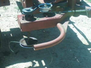
I also caught the swing arm on a post when backing up and had to rebuild the curving guard (a 1” electrical conduit elbow).
Trimming under the fence is a super feature of this design. On flat ground, you set the height to cut under the bottom wire and the tractor is driven so the swing arm guard is just past the center line of the fence. Slow speed is required as this strip is often the most overgrown, and keeping everything working smoothly is quicker than stopping to fix or re-string. As the arm touches a post, it swings back, the line cuts to the post and follows around as the spring brings it back to full extension. The difference between this and using a hand held device is a matter of several orders of magnitude.
I did discover that on steep sidehills where the fence is following the contour, the spread out wheels on the tractor can hit the tops of the fence posts before the arm gets all the way under the fence. Often these areas can be finished from the downhill side, but a few are too steep for that. I will rebuild the attachment points for the structural frame this winter to shift the unit over 6 inches to see if that solves this issue.
There are a few places where the tractor can't go, so a small amount of once-a-year hand work is required. I am adding simple poly wire gates at the ends of my single strand paddock wires to allow the tractor to trim the entire perimeter without having so many corners to navigate.
The clipper works very well in the centers of the fields. My goal is to follow the animals within a few days of their grazing to clip the tops of everything they did not eat. We use organic methods and past years where pasture clipping was not done allowed thousands of wild carrot, horse nettles, ragweed, and chickweeds to flower and seed. My 7 foot rotary mower could trim them but it was slow (achieving really 5 or 6 feet per pass) and could not deal with the fences. If you agree that anything the cattle won't eat is a weed, keeping those plants from reseeding is a plus. This fall we see very few weed flowers, and even a very late, warm fall has not been enough for many of them to become seed heads. We have had great luck over a period of years mowing bad weeds and then out competing them with interseeding and composted manure. This device is making that easier, quicker, and much more thorough. Looking across a field subdivided with paddock wires and seeing green grass flowing through without fouling the wires is a beautiful sight.
I used my existing drag this year to follow the clipper to break up cowpies for fly control and to spread the manure a bit. I will be making the trailer mounted drag and roller out of scrap metal and used haybine parts this winter. Now that I have worked through the trial of the clipper it seems that the best practice will be to follow the cattle within a couple days with the clipper, starting with all the fence lines, and then hook up the drag to finish the centers. The roller will be attached to the back of the trailer and will be lowered when the ground is soft for leveling, and when tillers are tall for crimping. Time will tell how often the combination of all three should be used. I was able to clip all the pastures 3 or more times this year and the results are great. Next year I will document weed growth over the seasons.
Another facet of our fly control will also be implemented next year as more paddocks are completed. On the checkerboard of paddocks with lanes dividing them in rows, we will skip a few paddocks on our daily moves. This will leave flies back at the pies and always give the cattle a clean place to lay. By the time we get back next door to a grazed area, the clipping dragging will be done. We are clearing shallow edges of our woods and building fences 20 feet back behind a few remaining trees to create a silvipasture system for shade. Planting these areas in red fescue and clover for shade tolerant ground cover provides clean, cool spots to lay. For this to be sustainable, the cattle need to be moved before they tear up the ground. We are working to have these areas in every paddock, for now we are limiting them to a couple days in a shared loafing area helps to keep the flies controlled. A further improvement will be shallow buried water lines to move the waters down the lanes in summer with quick connects near paddock gates.
To finalize the clipper for next season I plan on moving the pick points to offset the unit 6 inches, experiment with larger drive pulleys, try different cutting line, make covers for the top to keep clippings out of the belts, and repaint the primer coat with finish enamel before our field day.
Project objectives:
a) Build a front mounted mower using lightweight components to clip seed heads. Use existing heavy duty string trimmer technology, hydraulic motors and pump, belts and pulleys to allow a small tractor to effectively clip pastures and under fences. Build a pull-type trailer mounted drag with crimp roller to break up cow pies and roll seed tillers down to the ground.
b) Demonstrate daily rotation of beef cattle through permanent paddocks, showing the effects of the entire system of trampling, clipping, dragging, rolling, and rebound over a series of adjacent paddocks through field days in cooperation with local grazing groups.
