Final report for FNE24-074
Project Information
Through this SARE project, I sought to test a novel trellis-netting system to exclude birds and spotted-wing drosophila (SWD) from berry crops at harvest. I installed 14' cedar posts at the end of each row and extended a guy wire between them. This, alongside secondary lines strung between t-posts, allowed netting to be deployed across the crop rows. I trialed various materials for the project, seeking to evaluate options that would work for farmers to protect their crops, and troubleshooted design issues as they arose.
The project was successful in protecting the farm's honeyberry crop against cedar waxwings, but proved unsuitable for SWD with our raspberry crop. Conducting the project also revealed smaller design flaws that I was able to troubleshoot. The problems and their solutions will be discussed later in the report.
I provided outreach through social media, multiple farm walks with farmers and homesteaders, through one youth farm tour with the YMCA, and through personal conversations with growers in my work capacity at Fedco Organic Growers Supply.
This project seeks to:
- Construct and compare a set of plans for a post and wire zipline trellis support structure. It will be made from materials that growers can readily purchase through building and farm supply companies, as well as through 3D printing.
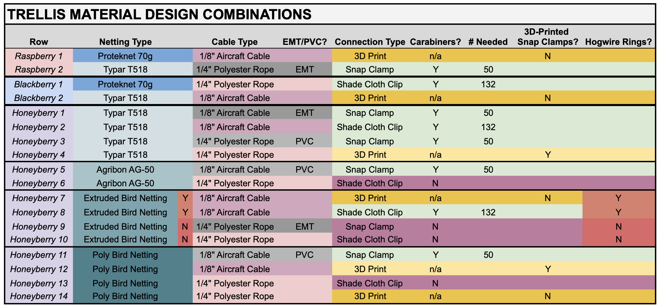
- Compare varying material option combinations for project construction to offer feedback to farmers looking to replicate the system. (See attached chart.) This will include qualitative observation as well as material cost/labor analysis.
- A 3D-printed model will be tested, and refined designs will be made freely available on the Internet for others to use.
- The efficacy of the system will be tested. Yield/yield loss data will be collected comparing SWD damage in the farm's raspberry and blackberry rows covered with 70g Proteknet and Typar T-518 against open field conditions. Yield/yield loss comparison will be collected in the honeyberry block comparing the various netted rows and open-field control rows for bird exclusion.
- Temperature/humidity data will be collected under the different netting materials and considered for correlation with crop yield differences.
- I will teach growers how to construct their own support structures through social media posts, two on-farm field days, and a MOFGA newsletter article in the second year.
Crop loss due to bird/insect pressure is one of the primary issues affecting berry farmers. A 2012 study by Cornell University calculated the average annual economic impact from bird damage to just five of New York State's fruit crops to be $16 million [Lindell 2014]. Similarly, farmers in the U.S. are contending with the spread of spotted-wing drosophila (SWD), a small fruit fly capable of laying its eggs into soft-fruited crops. It is estimated that SWD causes $500 million in economic losses to farmers in the United States annually [Roche, 2021].
Finding an appropriate solution to both cedar waxwings and SWD is at the forefront of my mind. SWD was especially challenging with my day-neutral strawberries and raspberries this past season, and the cedar waxwings consumed much of the fruit produced on our young honeyberry plants. With a vision of offering pick-your-own options throughout the summer, our farm is unfortunately also creating bridge crops for birds and SWD to remain on the land. A solution is needed that will work for our context.
Amongst available strategies, exclusion netting trellis systems are particularly effective against both birds and insects. Through SARE grants (FNE14-813/FNE20-963), Dale-Ila Riggs of The Berry Patch reduced crop losses in her blueberries and raspberries due to SWD from 40% and 25% respectively, down to 0.50% through a whole-field exclusion netting system of 80g Proteknet [Riggs, 2023].
At $25-28k per acre, however, whole-field systems have a prohibitive barrier to entry to some farmers, and require concentrated labor at key points to deploy and disassemble the netting each season. For Dale-Ila Riggs, it takes three people 8 hours to to deploy, and 6 hours to breakdown for winter storage [Callahan, 2022]. Indeed, a 2014 survey conducted by former UVM undergraduate Hannah Lee Link of northeastern berry farmers found that only 2.5% of respondents utilize insect netting to exclude SWD, with the primary reasons given for not doing so related to material costs and labor [Link, 2014]. While bird netting is significantly less expensive than Proteknet for exclusion, these cost considerations remain the same for installing any large exclusion system.
Link's research highlights the considerations a netting system would need to address for farmers to adopt the cultural practice. A general summation is that farmers seek an affordable system that can be built from readily available materials. They expressed preference for a large structure one could walk into versus netting over individual rows out of specific concern that the netting would be in the way for maintenance/harvest, and with the labor associated with deploying it. Machine access was strongly important to respondents, and that the system needed to be able to withstand winds and be easily deconstructed for winter storage.
A whole-field netting system is not ideal for our farm's setup. Beyond the already high cost of construction, our perennial crop rows are spaced further apart than is typical to allow rotational alleycropping of our strawberry crops. Labor limitations would also make deploying/dismantling a whole-field system a challenge for my farm. I believe, however, that the zip-line design I lay out in this proposal can be managed entirely by a single person after initial construction. The design will significantly lower the cost per acre to install versus a whole-field system, and, importantly, will address farmers' concerns of single-row netting being in the way for maintenance and harvest that Link's study described.
This SARE grant will investigate this novel trellis netting system. Drawing inspiration from childhood zip-lines, I propose to install something similar over our berry crops. I will bury posts at the ends of 18 perennial berry rows, and run a guy-wire spanning the crop row. Exclusion netting will then be attached to form a double curtain that can quickly be drawn and withdrawn from over the crop, and secondary support wires will create an internal canopy. The effectiveness of different hardware materials readily available to farmers and different netting options will be assessed during this project.
I believe this trellis netting design will greatly decrease crop loss from birds and SWD. Netting can be stored for winter wrapped around an end post, and I estimate a single person might deploy a row of netting in 20 minutes in the spring. It should take 10 minutes for harvest/maintenance after that. For farmers on a budget, or who have sub-acre crop plantings, I believe it is possible to install an exclusion affordably. This design will reduce crop loss and increase profitability in a manner that can address both SWD or bird predation.
Full Fork Farm has been in operation since 2016. Operating on 13-acres, the farm alleycrops 1.5 to 2-acres of strawberries annually amidst a diversity of perennial fruit and nut crops in an agroforest system. This shift from strawberries/vegetables to perennial agroforestry began in 2021, with the honeyberries being the first crop to begin marketable production. Currently, the farm grosses about $100k selling through u-pick, a self-service farmstand, and wholesale markets. The farm currently has three employees: one full-time and two part-time.
Cooperators
- - Technical Advisor
- - Technical Advisor
Research
The goal of this project is to test and evaluate a novel trellis system for excluding birds and spotted-wing drosophila from perennial berry crops, and to collect field data to support the project's conclusions. Data collection was proposed to begin in 2024, but design troubleshooting and the reality of the farm's production season led me to focus on construction alone last year. At this point, all the infrastructure is in place for installation of the netting this spring, but some adjustments are needed that will be discussed later.
The proposed trellis structure at it's basic is two 14' cedar posts installed at each end of a crop row with a guy wire suspended above the crop with netting attached that can be drawn over the crop like a curtain. The guy-wire passes through the cedar posts and is secured using duckbill anchors. Two t-posts are also installed at each end of the crop row with tensile wire tensioned between them. These secondary lines are intended to keep the netting away from the crop. Installation and the challenges I encountered will be discussed in detail in the next session.
Various materials are proposed for testing in this project to be able to offer feedback to farmers:
Improvements were made to the infrastructure in 2025, including: better securing the cedar posts for the primary lines; swapping the secondary lines from high tensile wire to 1/4" polyester rope; and installing new duckbill anchors for the secondary line t-posts to more effective locations.
2024 (Year 1)
The bulk of this section will explain the timeline, process, and redesign undertaken last season. Most went well and was straightforward in terms of installation, but a couple elements needed to be re-approached heading into the new year.
3D-Printed Hardware:
Heading into the project in the Winter/Spring of 2024 believing that we would be able to install everything in April, 3D-printing for the project began immediately after award of the project funding.
I took time to redesign the proposed 3D model because I realized the design would require filament supports successfully print the existing overhangs, which I wanted to avoid. This is the redesign I settled on for the project:
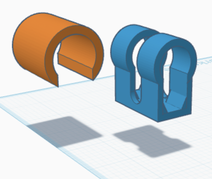
The new model can be printed without supports. Where the original design called for 15.25 meters of filament per paired hardware and a 1h2m print time, the new models require 6.93 meters and can be printed in 33 minutes (using the AD5MP). The model was printed with using PETG filament as planned with 15% infill density using both a Flashforge AD5MP and a Creator Pro 2 printer with .6mm nozzles.


EMT/PVC Hardware
Prepping the EMT/PVC hardware also began in March. 10' lengths of 1" PVC and 1" EMT were measured and cut down to 3" pieces. I use a chop saw for the PVC, and an angle grinder with a cut-off wheel for the EMT. The EMT conduit needed further processing to deburr the cut edges with a conduit reamer and chamfer, which added significantly more processing time than the PVC. The PVC, on the other hand, produced a lot of microplastic waste that was difficult to clean.


I used an inexpensive benchtop drill press to make holes in the EMT, PVC, and greenhouse clamps. The most efficient way to do this was to snap the clamp onto the EMT and PVC and drill through both simultaneously. This also ensured that the holes would align perfectly.

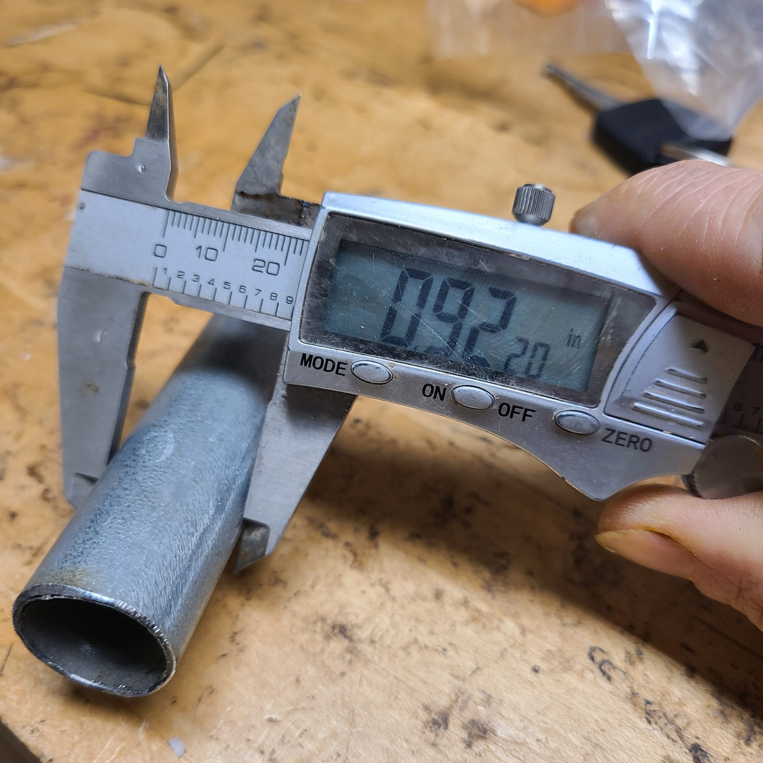
One concern that arose is the fit between the EMT conduit and the snap clamps is looser than that of the PVC. The diameter of the EMT is actually .92" not 1". I will be assessing whether this is an issue in the field.

Spring - 2024
Installing Cedar Posts & T-Posts


West arrived in April and to assist in putting energy into installing the 14' cedar posts. We used a tractor-mounted post hole digger with an 18" auger to initially excavate the holes. Most needed additional manual labor to remove soil and get them down to 36-48" in depth. We ran into significant ledge with a few holes, and used a hammer drill powered by a generator to break deeper into it. A tamping bar and level were used to set the posts.
8' t-posts were installed inset from the cedar posts to help support the fabric away from the crop using high tensile wire. Issues arose installing that tensile wire, and will be discussed later in the report.
Drilling the Guy-wire Holes


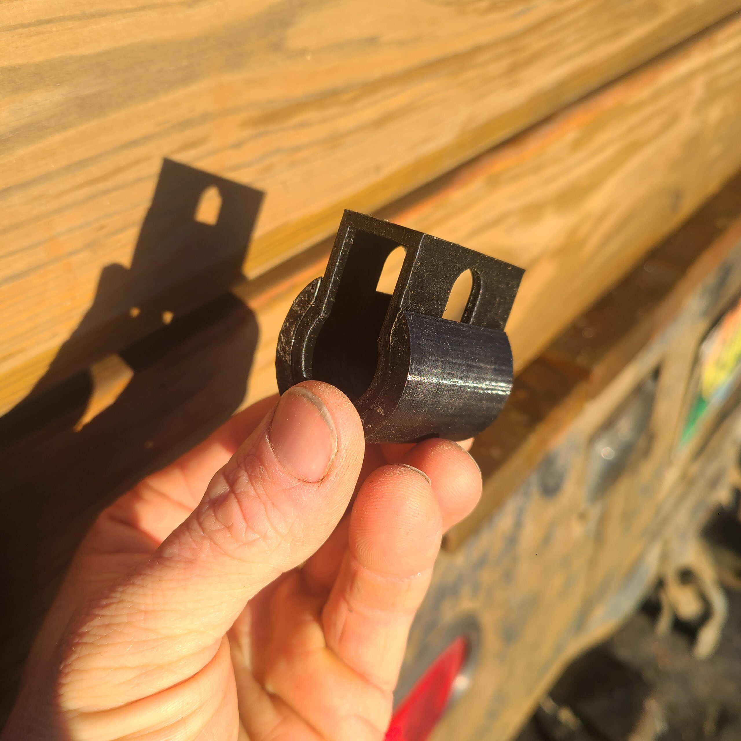
A 1" diameter hole was drilled through the post at a height of 10'. I found that running the guy-wire directly through the drilled hole created problematic rubbing. It was causing the rope to fray and the air craft cable to cut into the cedar post and jam. The solution to this was creating 1" EMT conduit inserts for the hole (shown in the photos above).
Each EMT insert is a custom length because the diameter of the cedar posts is variable. For each post, I would insert leftover lengths of EMT, mark it with a sharpie where it needed to be cut. After cutting the pipe with a pipe cutter, I used pliers and the drill bit reamer on the cut end to smooth any sharp edges, then tapped it into place with a hammer.
Duckbill Anchor Installation


The next step in the process is to install the duckbill anchors 4' away from the cedar posts. We found that the best installation method is to first use a t-post pounder to set the anchors, then switching to a 6 lb. sledge once the t-post pounder makes ground contact to finish it off. This proved quickest method, with least wear on the body.
Installing the Guy-Wires


The first step to installing a guy-wire is to pull out the guy-wire line. We did this off the tractor bucket using EMT conduit and chain to elevate the spools. I climbed a ladder to thread the line through the first insertion hole, then walked down and repeated this step using a second ladder on the other side. The important thing is to maintain a steady pace as you walk but then slowing down while maintaining tension to the rope so it doesn't over-spin on the spool when you stop at the end of the row.
At the end of the row, I looped the line through the duckbill anchor and secured it off. For the aircraft cable, this is done with two 1/8" steel rope clips. For the poly-rope, this is with a bowline, as an easy to undo knot. For the aircraft cable, it requires two steel rope clips (see photo above). The orientation of the steel rope clips is important. The saddle should be against the "live" end, while the nuts should be on "dead" end.
Bolstering the Cedar Posts for Wire Installation

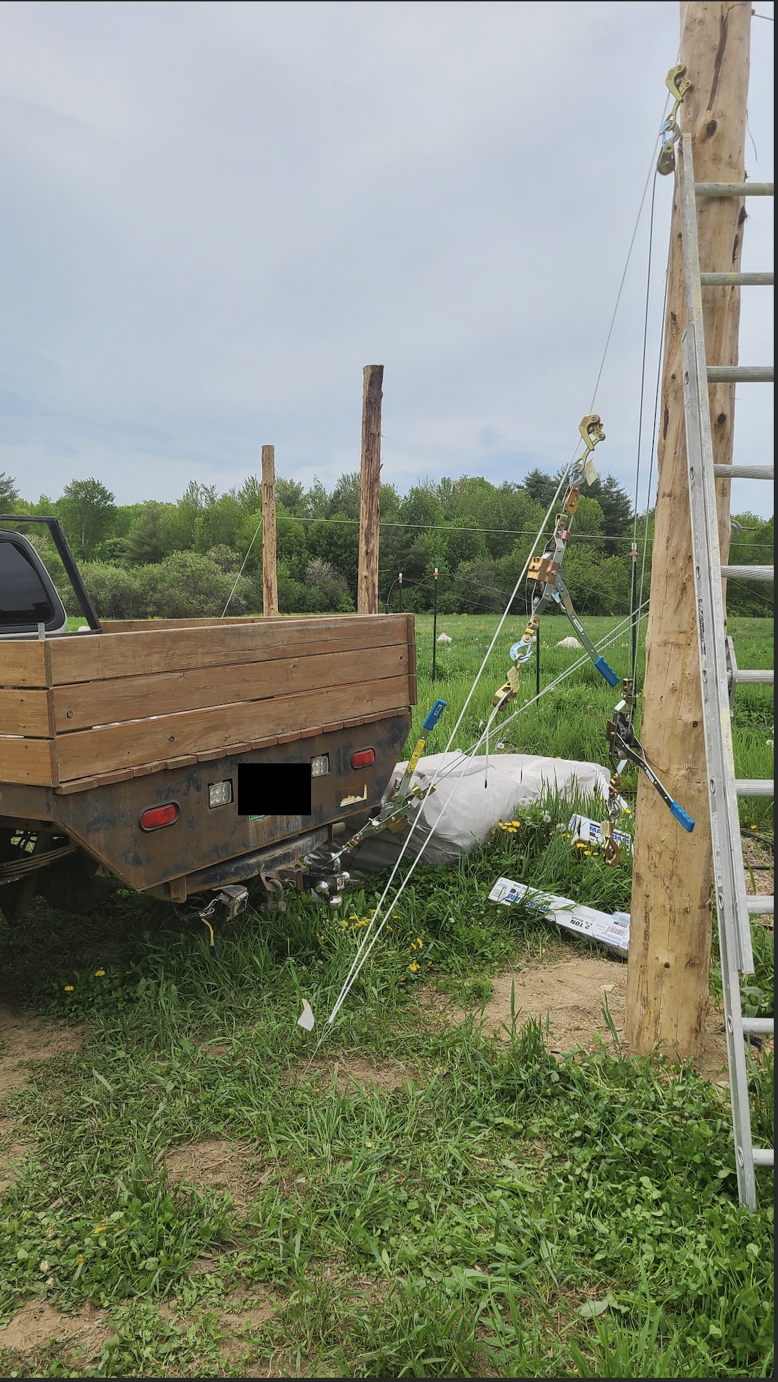
The next step is to insert a structural screw on the inside of each of the two cedar posts, in line with the crop row. This is to ensure that the cedar posts aren't pulled inwards when tensioning the guy-wire. I parked a large vehicle on each end of the crop row, and ran a come-along winch from the vehicle to the structural screw and ratcheted it under tension.
Once the cedar posts are well-anchored, I fed the loose end of guy-wire through the duckbill anchor to tighten the line. The wire thimble hardware, placed in the wire loop of the duckbill anchor, is critical for this step. Without it, both the aircraft cable and the rope struggled as they were tensioned. The thimble allows them to slide easily.
Tightening the Guy-Wire
Tightening the guy-wire requires two come-along winches and four one-ton cable grips. The cable grips are attached to the come-alongs, and make it possible to grab on and tension the guy wire. You tighten the cable as much as possible by hand, then climb a ladder leaned against the cedar post to attach one end of the come-along to the end of the guy-wire. The other end of the come-along is attached to the loose end of the rope. This then allows you to ratchet the come-along and pull the guy-wire tighter.
However, this needs to be done several times. This is where the second come-along setup comes into play. With the second winch, you leap frog over the first come-along and continue to tighten the line. When the tension has slackened to the first come-along, you can remove it safely. This leapfrogging process needed to be done at least three times. The poly-rope needed more repetitions than the aircraft cable.
Summer 2024
T-Post Secondary Line Installation
Multiple issues came up installing the high tensile wire as secondary lines for the t-posts.
First, it was impossible to pull the tensile wire strongly enough by hand to tighten the line between the t-posts, and the 1-ton cable grips used for the guy-wires were insufficient. The cable grips are unable to latch onto the thin, smooth gauge of the high tensile wire. A fence strainer is the tool needed for the job.
Step One is to cut notches in the top of the t-post using an angle grinder and cutoff blade. The Lockjawz product I purchased for this step was not strong enough for the force applied by the high tensile wire. This was the solution. (see below).


Step Two was to install a duckbill anchor in the ground and secure the t-posts using high tensile wire with loops crimped on each end (see above). In retrospect, as I will describe later, this is not how I would recommend securing the secondary lines. Better would be to install one duckbill anchor per t-post and have its installation location be in line with the secondary line.
Step Three is to draw out tensile wire along the length of the crop row using a Spinning Jenny, and crimping loops on each end. These loops are also inserted into the notch of the t-post. (see above, as well)

Step Four is to cut the high tensile wire somewhere along the line, and use a fence wire strainer to tension the secondary wires, then tie a high-tensile quick knot. This is a technical fencing knot, but one with tutorials readily available on the Internet.
Troubleshooting...
Note: It proved important for me to do this step to both secondary lines simultaneously because I connected both secondary lines to a single duckbill anchor. I did this thinking to save on material costs, as well as to have fewer areas I needed to mow around carefully in the future, but it ended up causing frustration and cost additional labor. Tightening just one line began to warp and bend the t-posts in towards each other due to the duckbill anchor placement and the forces put upon them. I had to pause this step of the project and order a second wire strainer, and to consider how to prevent the t-posts from collapsing towards one another.
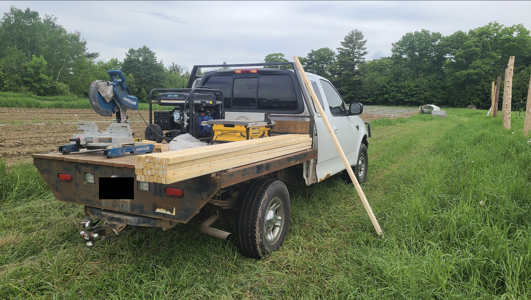
- What I came up with as a solution was to purchase 8' 2x4s. These were then custom cut and notched in the field to fit between the t-posts and secured using metal tape and screws (See photo below for 2x4s in place. See photo above for a photo of the metal tape used to secure the 2x4 to the t-posts.
- I brought my chop saw and table saw into the field on my truck with a generator and cut notches in the 2x4s to fit securely to the t-posts. These steps occurred between Steps Two and Three, but I do not believe are the best course of action.
- When the second wire strainer arrived and both secondary support wires were tightened simultaneously, the t-posts with the 2x4s between them exerted equal force upon each other, which prevented them from collapsing inward.
Further Troubleshooting, and potential solutions...

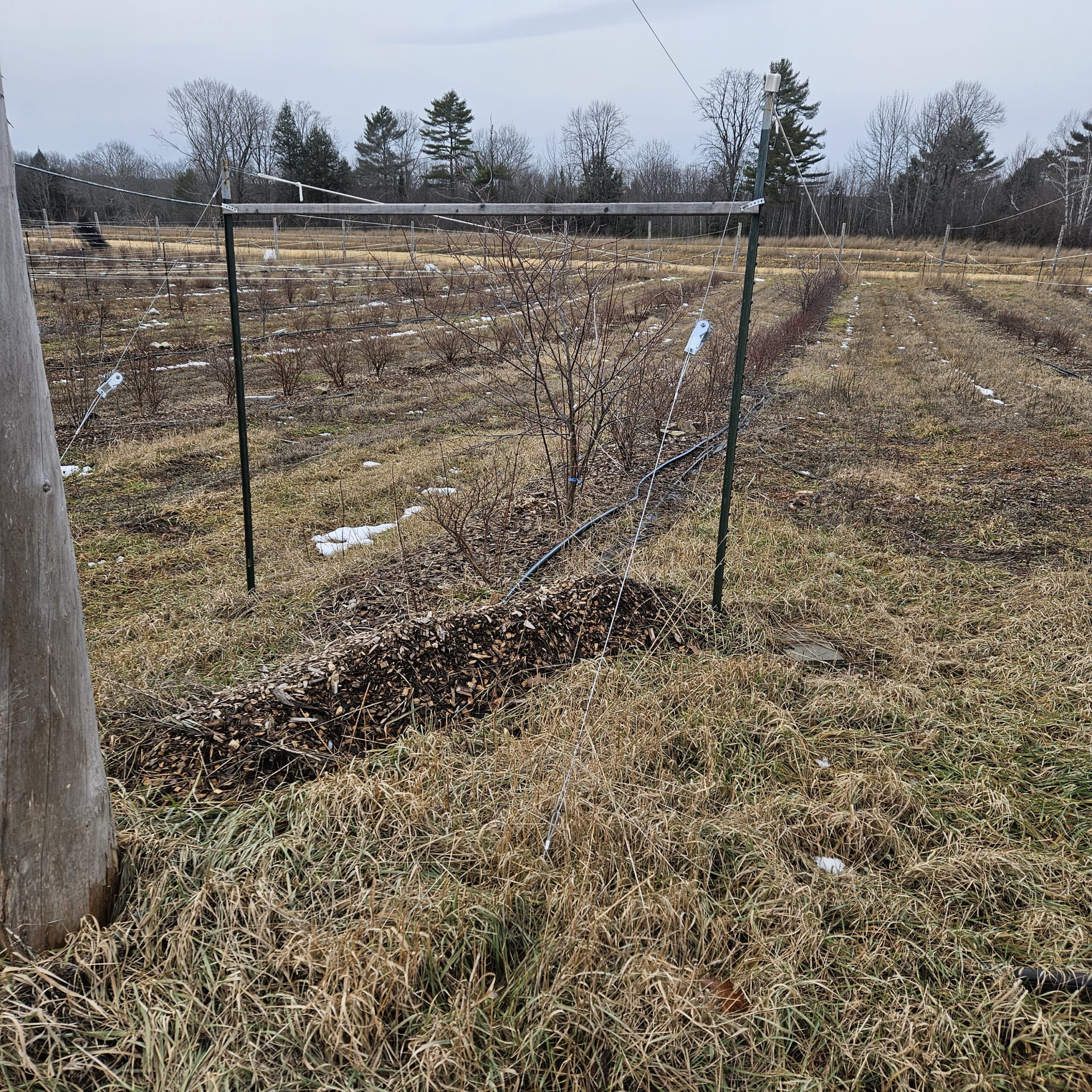
While the t-posts no longer bent inward towards each other, a new problem presented itself: The tension of the high tensile wire caused them to lean inward toward the crop (see above). At the time I felt this was acceptable, but increasingly feel that the correct direction is to install one duckbill anchor per t-post set back at least 6'-7' (the height of the t-post). This small change should eliminate the t-posts bending in either direction, will no longer require the 2x4s, and should allow the high tensile wire to be put under greater tension than it currently can be under.
Netting Installation
West's and my time together ran out, and installation stalled from May through July with the demands of the farm season. I underestimated how long the installation would take and the way in which the farm season would affect the project. It took until late-summer for me to have the time to put more energy into the project and get the first netting installed (Typar T518).
To install the hardware, I first drew the row cover out along the ground, followed by a 300' tape measure. The Typar T518 was folded in half with a sewn seam at the center line that I lay along the tape. I walked along with a spray can to marked every 4' where the hardware would be installed.

Shown in the picture below is all the hardware needed by the white paint marks. I arranged the row cover to be able to reach underneath and install the EMT conduit hardware and snap the clamp into place. A nail was used to poke a hole in the row cover for the eyebolt to easily pass through the fabric. I tightened the washer and bolt with a ratchet wrench.


From there, it was a relatively easy job to climb a ladder and attach the "netting" to the guy wire.


Future troubleshooting...
There was some noticeable sag in the guy wire from the weight of the Typar T518, which is a pretty heavy fabric. I noticed the weight showed some pulling on the cedar posts, so have installed duckbill anchors that I plan to run tensile wire from to help anchor and prevent this from happening.
Another issue, and perhaps the largest for the project, is that the row cover very much caught wind. To the point that a strong autumn wind picked it up and tangled it drastically. The t-posts ripped through the fabric in some places. I will troubleshoot the anchoring, but this indicates that this system might not be well-suited to "netting" options that don't allow significant airflow. I may limit the number of rows I install row cover to as I assess. If it is the case, this system may only do well for excluding birds not SWD.
A last final issue. The blackberries I was establishing on the farm that were to be part of this project did not fare well last season. I will assess once they break dormancy in the spring, but I may choose to eliminate their consideration from the project.
West will be arriving back this April to put more energy into the project. We will anchor the cedar posts, modify the t-post setup, and installing netting. I anticipate being ready to collect harvest and field data for this coming season.
2025 (Year 2)
April 2025: West Lenz visited the farm and helped complete the infrastructure for the netting system. We made adjustments to the infrastructure to improve areas with design flaws.
- Freeze and thaw demonstrated that some cedar posts were not properly tamped in 2024, so time and labor went into correcting this.
- As well, a few cedar posts had bucked inwards in part to the frost heaving, and in part to the continued tension from the guy-lines. To solve this we installed new duckbill anchors 5' out from each t-post in line with the crop row and tensioned high tensile wire from the top of the cedar post down to the new anchors.
- This did work, but in a perfect system I would install the anchors 9-10', matching the height at which the tensile wire was attached to the cedar post. This was not possible as it would impede the farm's vehicle paths.

- 2024 demonstrated that high tensile wire was the wrong material for the secondary lines because it wasn't physically possible to tension the wire enough to be effective for the project. I swapped the tensile wire for 1/4" polyester rope, which was absolutely simple to install. It was unspooled similarly to what was done for the rope used for the guy wires in 2024, and tensioned using two trucker's hitch.
- I much prefer this to the tensile wire because it was quick to install, and was equally quick to loosen. This made navigating the crop rows in the fall to spread mulch simple with nothing in way, which addresses one of the primary concerns farmers express with netting systems that utilize materials like hoops.
- We installed new duckbill anchors in line with the t-posts/secondary lines on each end of every crop row: four duckbill anchors per crop row. This orientation provided the proper counterforce
- We initially installed the duckbill anchors for the secondary line posts centered in line with the crop rows - one for each pair of t-posts on each end of the crop row. This was a mistake. Under tension, the t-posts bent laterally, caving towards the crop row. My fix for this in 2024 was to install wood posts between the t-posts. It worked passably, but was solving a symptom instead of addressing the problem.
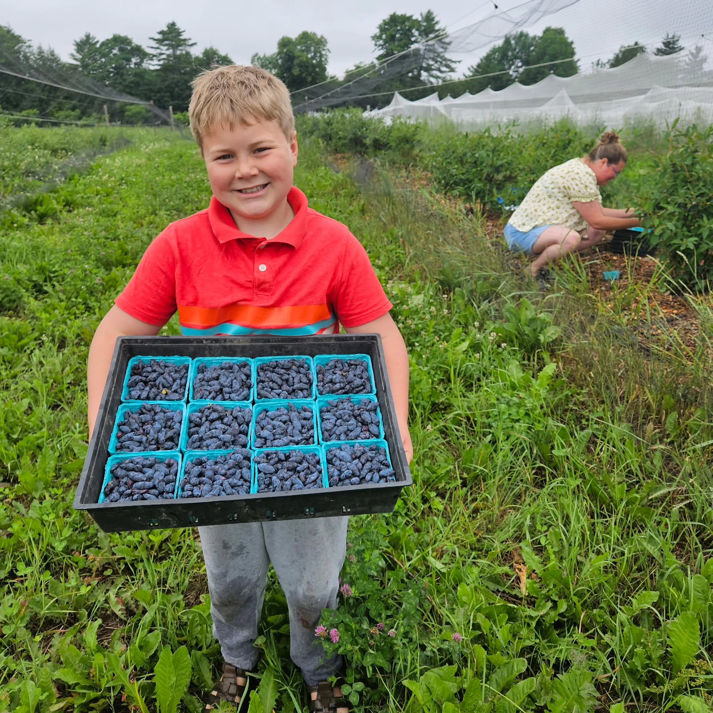
June 2025: Nets were installed in June ahead after fruits had begun to develop but before they were ripe. Cedar waxwings had already started to gather at the farm. Time trials were conducted for deploying the system, and harvest yield data was collected. Sensorpush units were deployed, but, unfortunately, the temperature/humidity was lost alongside my phone. I tried to recover it but was not able to do so.
- While I'm disappointed about the data loss, my consolation is that these sensors were included in the project primarily to test the difference between temperature and humidity under the ProtekNet, Typar, and Agribon in comparison with the bird netting options. I can only provide an anecdotal account, but there was no significant difference in temperature or humidity between the two bird netting options.

July 2025: Harvest started June 29th, and continued throughout the month of July. In total, 614 lbs were harvested from the eight experimental rows. A 12 half-pint flat averaged 5.3 lbs, grossing ~$5900 for the farm. This is at most a quarter of what I expect to harvest once the plants are mature, but after losing multiple harvest birds, it's a welcomed start. In comparison, the crop rows that were uncovered literally had zero harvestable yield. It was entirely eaten by the cedar waxwings before we could harvest.
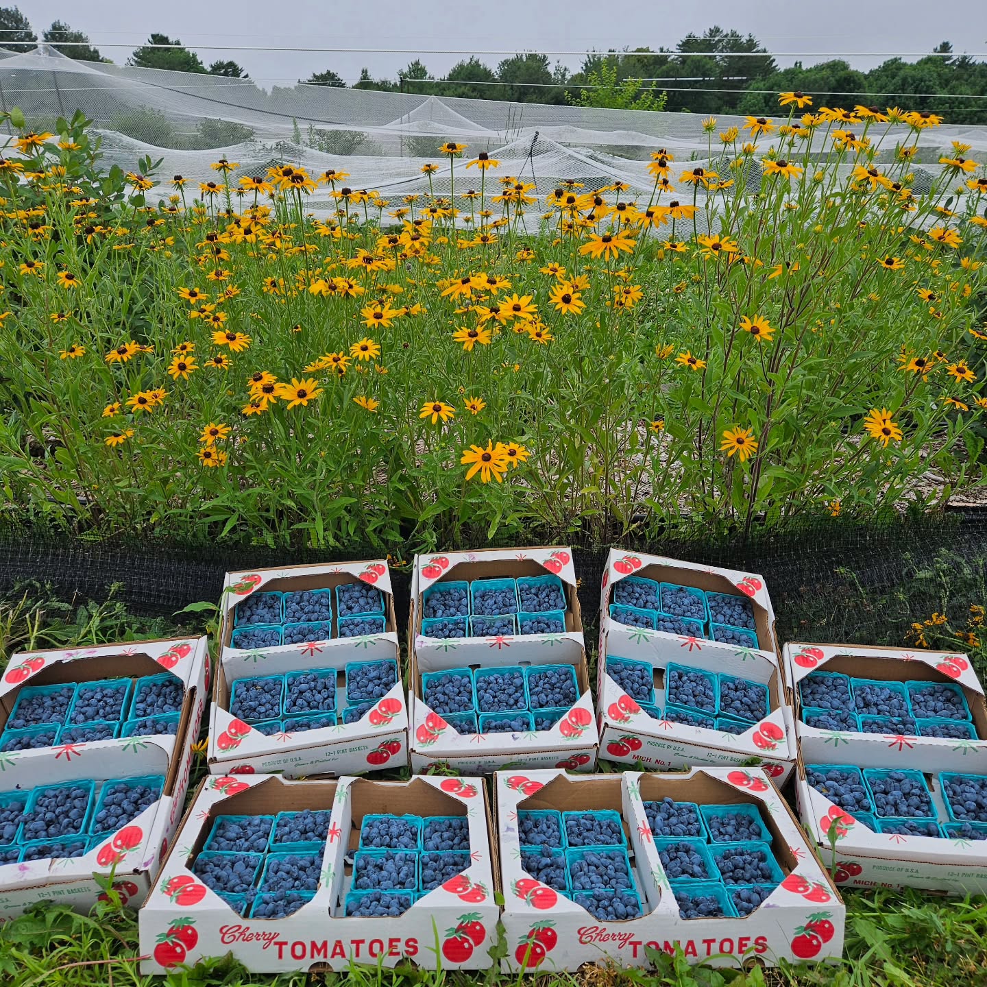
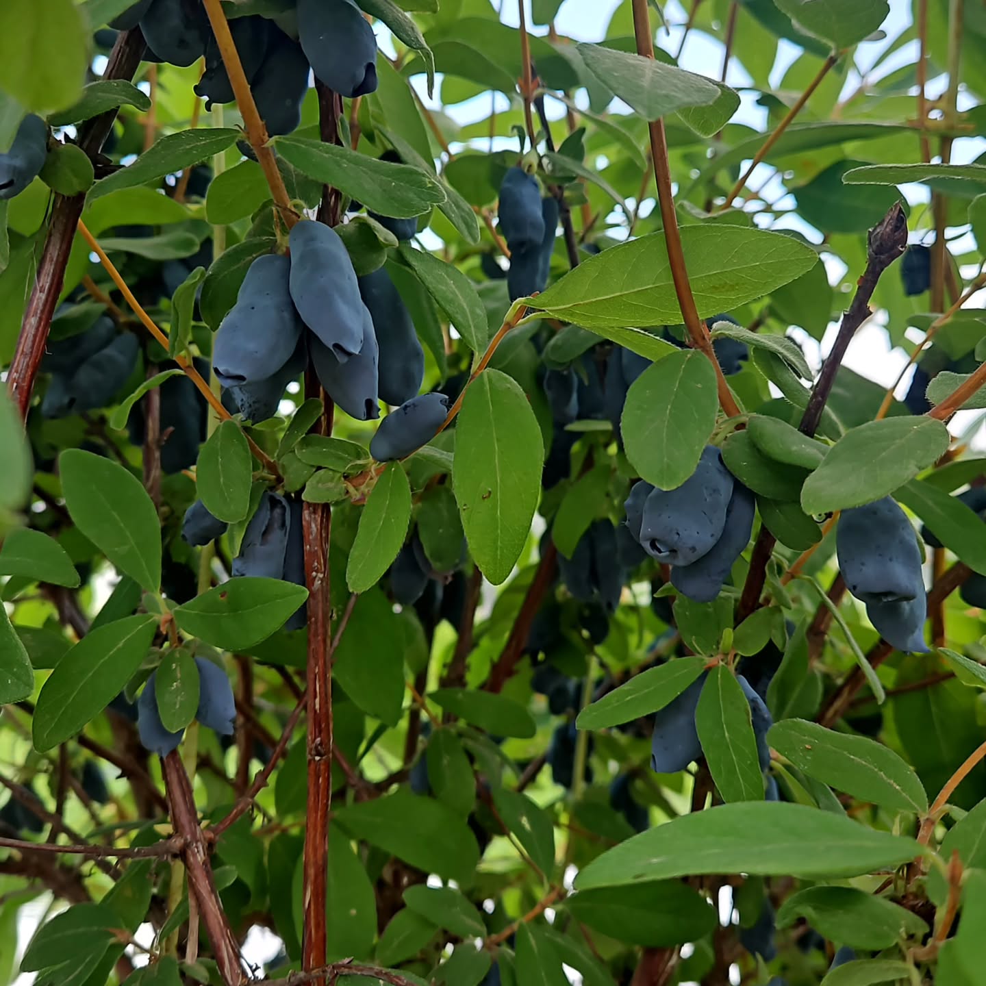
- To note for potential honeyberry growers: the covered rows in this experiment represent the mid- to late-season honeyberry varieties on the farm. This includes: Blizzard, Beauty Beast, Strawberry Sensation, and Giant's Heart. Growers in Zone 5a should anticipate harvesting berries in mid-June.
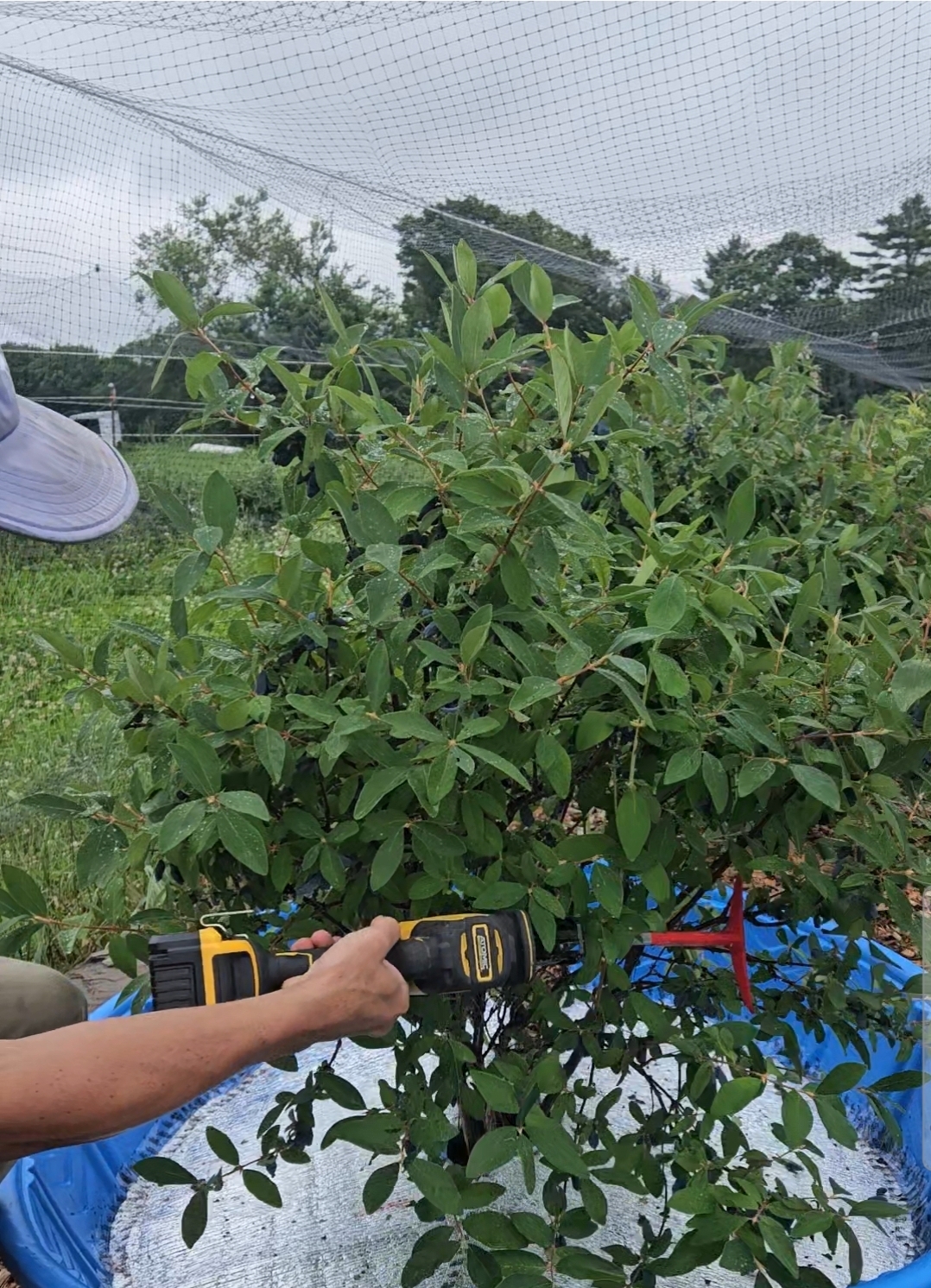
- Harvest was conducted via a mix of hand-picking from the plant, and mechanical harvest using kiddie pools, a battery-operated saws-all, and a 3D-printed attachment to shake the berries off the bushes. Handpicking provides better quality berries, but takes more time. Mechanical harvest fruit quality also depends on variety. I am getting to know each variety, so cannot provide detailed information.

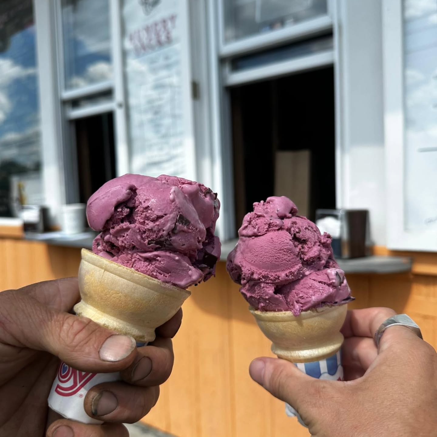
- We experienced negligible waste yield within the netted rows. All b-grade berries were sold to a local ice cream parlor and to a meadery.
Fall 2025: At the end of the growing season, I removed most of the netting from the wires, wrapping one to trial how it would fare over winter.

- This process was relatively simple, though slightly cumbersome. It would be more efficient doing the task with two people.
- The ease of pulling netting to one end depended on the type of connection used (carabiner, EMT, PVC, shade cloth clamp, 3D-printed part), but as well as the guy-line type (polyester rope, aircraft cable). It took 10-15 minutes to pull the netting to the end of the row, and another 5-7 minutes to gather and secure the netting for the season's end. I was not able to wrap it around the cedar post as I had imagined in the project proposal. Instead, I just secured the netting to the cedar post without wrapping it.
- In my experience, the carabiner, EMT, and PVC pulled easily. The shade cloth snap clamps alone (without carabiners) had a tendency to catch on the line, which was frustrating. The 3D-printed part was somewhere in the middle, but showed abrasion wear over the course of the season. Nylon filament, which has a lower friction coefficient, would probably be more appropriate.
- It is January 2026 as of writing this. We have had a couple heavy snowstorms and it has held up fine.
- The ease of pulling netting to one end depended on the type of connection used (carabiner, EMT, PVC, shade cloth clamp, 3D-printed part), but as well as the guy-line type (polyester rope, aircraft cable). It took 10-15 minutes to pull the netting to the end of the row, and another 5-7 minutes to gather and secure the netting for the season's end. I was not able to wrap it around the cedar post as I had imagined in the project proposal. Instead, I just secured the netting to the cedar post without wrapping it.
Observations & Discussion
For protection from birds, this project proved to be a definite success, and infrastructure that will be utilized on the farm for years to come. I have every intention of applying the lessons learned here to expand the netting system over rows that do not yet have it. Based on my experiences, these are the primary lessons learne...
Material Considerations
- The best material choices in my experience are the aircraft cable using woven-poly bird netting that is attached with a combination of shade fabric clamps carabiners.
- PROS: This combination offers the best durability; the quickest hardware installation to hang the netting with minimal pre-prep needed, and minimal friction drag between the hardware and aircraft cable.
- CONS: The carabiners did not fit the loop that is part of the shade cloth clamp. Pieces of mason twine needed to be cut, threaded, and tied to complete the connection. This is the only pre-prep work needed for this combination, and was easy, but a different type of carabiner my be able to eliminate this step.
- Issues with certain materials:
- The Proteknet, Typar, and Agribon are not appropriate for this system. Their fine weave causes them to catch wind and act like a sail. This system is not appropriate for excluding spotted-wing drosophila
- As mentioned, friction abrasion was noticeable on the 3D-printed clamps. Nylon filament, which has a lower friction coefficient, would be recommended. As well, the 3D-parts needed to be slightly thicker to boost their strength. I will be providing an updated .stl with this final report.
- Some wear was noticed on the polyester rope guy-wire from friction abrasion at the points where it passes through the cedar post. I can consider a few ways to lessen this, but am still recommending aircraft cable for the guy-wire for greater durability if it can be afforded.
- Installing the duckbill anchor for the guy-wire further away from the cedar post (9-10') would change the break angle to 45°, lessening the friction.
- One could forget about the duckbill anchors for the guy-wires and tension them in air. This downside of this approach would be sacrifices of both ease and safety that accompanies tensioning lines at ground level vs. 10' in the air.
- The extruded bird netting was much more prone to tangling and breaking. A neighbor with a lot of homesteading experience spoke to its short lifespan due to UV exposure, and its tendency to break apart into microplastics that pollutes one's growing area. For these reasons, I cannot recommend it.
Design Considerations
- 200' rows are too long for this system, as there was quite noticeable sag in the guy-wire at that distance. My recommendation would be 100'-125' crop rows maximum, though further testing is needed for a definitive number.
- For my 200' crop rows, which are already established, I will be trialing a temporary wood support at the crop row's midpoint made of a 2"x4" that catches and elevates the guy wire in 2026. If this fails to solve the issue, I will install another cedar post.
Time Trials
As mentioned in Previous Research section of this project's proposal, deploying a whole-field netting system takes three employees 8 hours to deploy and 6 hours to breakdown per acre according to Chris Callahan's work. 41 hours in total for the season. My time trials indicate that it would either take:
- Approx. 4o minutes to setup and 20 minutes to breakdown per row, if a grower were installing the net after having completely removed the netting form the guy-wire for the season. A total 21 hours of labor for the season, capable of being conducted by one person.
- OR - and this is estimating -20 minutes to setup and 20 minutes to breakdown per row, if a grower had secured the netting the previous season to the cedar post. A total of 14 hours of labor per acre for the season, capable of being conducted by one person
This difference represents significant labor allocation and cost savings in comparison to a whole-field netting system.
Considering Neighbor Relations
A common solution berry farmers employ to deal with birds at acre+ plantings is either a sound cannon or bird-distress recordings. These can offer a less expensive means to protect the majority of a crop, but comes at a cost. These systems are a nuisance for neighbors, for u-pickers and, at least in my experience, the farmer. Before conceiving of this SARE project, this was the option that I felt was viable for my operation. I'm glad to have had the opportunity to put together this system. For farmers wanting to avoid the sound pollution that aural deterrents bring, the trellis netting system trialed in this project is an option.
Cost to Install
Based on the budget I put together for this project, I estimate that it would cost $9,604.00 in materials to install this system on an acre of land. Tools and additional materials like tractor fuel would cost an additional $625.00. (This does not include the tractor post hole digger, or field tools like tamping bars and shovels, or power tools, which were already on-hand.) I estimate labor to install the system at acre based on my budget expenses to be 200 labor hours. At $20/hr., this comes to $4000.00 in labor expenses.
The grand total to install this system on an acre is $16,429.00. For comparison, an acre of a full-netted system using wood posts would cost $25,379 according to Dale-Illa Rigg's work. This is with 139 labor hours and a pay rate of $20/hr.
The result of conducting this research project is a working system to exclude birds from berry crops, but not spotted-wing drosophila from late-season cane fruit. Cedar waxwings have been a persistent problem for the farm, and this exclusion system offers a way to easily deploy netting and protect a crop. It takes up front work to install the posts, run the lines, and install the hardware, but then offers an efficient and cost-saving method to protect one's crop.
2025 was the first year I was able to get an appreciable yield from the honeyberries, and not having the birds mobbing the bushes was a huge personal relief. With 900 honeyberry plants, estimating a yield of 5 lbs. per mature plant at the low end of the spectrum, I estimate a gross income of $43,301. (I see yield estimates for honeyberries ranging from 4-10 lbs. per mature plant.)
Evidenced by the rows left uncovered, which had no harvestable fruit, this is a system that I will certainly be expanding to protect more crop area on my farm, and will continue to share information about it with other farmers.
Education & outreach activities and participation summary
Participation summary:
Outreach was conducted through social media posts, tours with several farmers over the course of the project, as part of a youth tour in conjunction with the YMCA, and conversations with u-pick customers. Additionally, my work at Fedco Organic Growers Supply afforded many informal conversations with customers who were experiencing trouble with their berry crops. Two of these conversations - one with a farmer - seemed to particularly resonate.
The numbers of people who participated in learning presented above does not include those who engaged via social media. This number was 298. I will be making another post with the final report linked at the conclusion of this project.
Learning Outcomes
The majority of outreach success was from social media. For the farmers and handful of homesteaders I connected with about this projected in a personal way, the outcome of the conversations was exposure to this system as a potential solution for crop protection. One customer from Fedco I spoke with seemed particularly taken with the idea for their small home-scale setup, but I unfortunately did not get their contact information to be able to follow up.
Project Outcomes
This project without a doubt has had, and will continue to have, benefits to the farm. In place now is an easy-to-deploy netting system that excluded the cedar waxwings from consuming the honeyberry crop as it ripened. This led to a harvestable yield, and the relief knowing the crop was protected.
Funding for this project also afforded the latitude to make mistakes, to trial solutions, and to create a roadmap for 0ther small farmers to follow. SARE funding allowed me to expand the design concept, and figure out what did and did not work, and I believe that will allow other farmers to implement a similar system for their operations with confidence in its success.
A component that I actually think was helpful to this project's success was SARE's grant proposal process. Having to verbalize the project's steps to the evaluation committee, being sure to consider and account for every material need, and estimating the labor requirements contributed to the project going fairly smoothly.
Overall, the project went well. I've stated it in other parts of the final report, but the following are aspects of the design that required revision or that I would recommend based on experience working with the system:
- The fine-mesh needed to exclude an insect as small as SWD also meant that it caught wind and acted like a sail, and is not recommended.
- A crop row length shorter than 200' is recommended due to a noticeable sag in the guy wire from netting weight. 125'-150' would probably be more appropriate.
- For my crop rows, which are established at 200', I will be installing a mid-way support post in each crop row. This will either be another 14' cedar post, or some sort of temporary post using stick lumber.
- The best combination of materials, in my opinion, is commercially-available snap clamps in conjunction with carabiners, strung on an aircraft cable guy-wire, using poly bird netting. These offer the best durability, quickest installation, and the ability to remove the netting without taking down the guy-wire.
- The one downside is that loops of string or rope were required because the carabiners couldn't fit through the snap clamp eyelet on their own. It's possible that a different/larger carabiner could work. I used pieces of mason line, which was effective.
- The PVC/EMT clamp setup with carabiners works perfectly, but requires a lot more labor to prepare the hardware.
- I initially thought I would be able to tension the poly-rope main guy-wire using just trucker's hitches, but both the aircraft cable and the poly-rope primary wires required use of two come-along cable puller winches and four one-ton cable grips leapfrogging over one another to bring it to adequate tension.
- The secondary lines to hold the netting away from the crop is important, but high tensile fencing wire was not the appropriate material. It was not possible to tension it appropriately for this project.
- My solution was to use poly-rope, tensioned using two trucker's hitches. A benefit of this choice is the ability to quickly take the line down for crop access with machinery. For myself, this made mulching the honeyberries with the tractor this fall far easier.
- Inserting the EMT casing into the cedar post is a critical step to prevent the guy-wire from cutting into the cedar post an jamming up. Install it at a an angle, following the path the guy-wire will travel to the ground anchor.
- Had I the room, I would install the ground anchor for the guy-wire 10' away from the cedar post than I was able (as far away from the cedar post as the height of the hole bored into the cedar post for the guy-wire).
- For the secondary line, the ground anchor should be in line with the secondary line itself, not in line with the crop/cedar post as we had initially installed it. Installing it improperly caused the t-posts to bend inward. Doing it as described corrects this.
- The 3D-printed part worked, but was not durable enough. Some parts broke in use, and I noticed wear where the part made contact with the guy-wire. A stronger, updated design can be accessed here.
Though it's unfortunate this system turned out not to be appropriate for excluding SWD, overall I accomplished what I set out to do. The farm now has a netting system I'm confident will serve us for many years, and I will certainly be replicating it across other crop rows in the field.
This netting-exclusion system is most appropriate for small to medium-sized farms needing to protect their berry crops from birds. For less capital investment and labor than a full-field system, growers can ensure they can obtain a harvested yield. Additionally, I could see this also working well for homesteaders with small backyard plantings who struggle with birds getting to their fruit before they can.