Final report for FNE21-989
Project Information
This project sought to improve upon deploying deep water oyster cages by assisting in the placement and by evaluating a tool to visualize the cage distribution on the bottom.
Releasing filled oyster cages from the surface in deeper waters is problematic as the farmer has no control as to the orientation of the cage when it rests on the bottom. To improve upon this condition, two tools were evaluated for dropping cages from the deck of a vessel. The first was to attach buoys to the top of the cage to act as a parachute in holding the cage in the proper orientation as it freefalls to the bottom. Numerous buoy configurations were tested with limited success. The second was to attach a line to the top of the cage and lowering the cage with a controlled descent while ensuring that the line could be released from the cage after the drop to prevent vertical lines from proliferating on the farm site. Using a looped line through the cage top proved to be 100% effective in ensuring the cage landed on the bottom in the proper orientation while allowing the line to be easily retrieved from the deployment after the cage release.
The second objective with this project was to evaluate routinely available fish finder technology to locate and identify oyster cages on the bottom in deeper water. A Humminbird Solix 15 fish finder with integrated down- and side-imaging sonar was adapted to allow for portability of the unit between work boats and utilized to generate a mosaic image of the bottom of the shellfish farm using a dedicated software package (SAR Hawk) to integrate the side-scan data into a complete picture of the bottom. The Solix 15 proved to be an effective tool for visualizing oyster cages on the bottom as well as other structures, including debris left by previous managers of the farm.
This project seeks to improve upon deploying deep water oyster cages by assisting in the placement and by evaluating a tool to visualize the cage distribution on the bottom. To achieve this goal, we propose the following objectives:
- Develop a means to ensure that cages released from the surface will land on the bottom in an orientation to ensure optimal growth of the seed within. By testing two different means to maintain cage orientation as it falls, we will evaluate the efficacy of promoting an upright landing and will monitor the cost in terms of both time and expense to apply the deployment techniques. The success of the enhanced cage release, in terms of proper cage orientation, will be assessed by way of observing the orientation of the cage as it lands on the bottom, the time of freefall of the cage to the bottom, and the cost of any modifications required to improve cage orientation with landing.
- Develop a method to visualize the orientation and placement of cages on the bottom using commercially available “fish finder” technology. With the application of side-scan sonar, the farmer may observe a three-dimensional representation of the array of cages on the bottom with fine enough resolution to monitor both overall placement relative to other cages and the orientation of the cage as it lands.
This proposal addresses the USDA-SARE need for “improved productivity” leading to “an increase in net farm income”. Additionally, increasing the number of oysters in the water at any location underlines the role oysters play in mitigating nutrient additions and improving compromised marine habitat (Parker and Bricker 2020). Any advancement in oyster farming technology leading to more oyster farms addresses the USDA-SARE need of “improvement of water quality and protection of natural resources.”
Diversifying farm production is a critical strategy to enhance the success of a farm. Farm crop diversification leads to increased capacity to mitigate financial and production risks associated with market volatility/saturation and environmental changes (Lancaster and Torres, 2019). Blue Stream Aquaculture is diversifying its product line through establishing Blue Stream Shellfish LLC (BSS) that is engaged in farm production of the eastern oyster (Crassostrea virginica).
Entering into oyster aquaculture in Massachusetts is a challenging undertaking with each town regulating its own shellfish resources. In many locales, the available space conventionally used to farm shellfish, i.e. intertidal and very shallow sub-tidal (<2 foot depth at low tide) waters is becoming fully occupied or is limited due to physical/natural resource/social constraints. Many of the opportunities to initiate an oyster farm have now moved to deeper off-shore locations, especially south of Cape Cod with limited availability of intertidal/shallow sub-tidal space (Ward 2012, CEI 2018).
Deeper locations reduce the risk of interference to crop production from an environmental problem, such as shore-side sewage or petroleum spills; from tampering by inadvertent or intentional human activities, including poaching of the crop; or from growing reticence from upland land-owners to allow farming in their viewscape or near-shore recreational areas (Cheney et al. 2010, Beckensteiner et al. 2020).
Shellfish farming in deeper waters requires a new set of technologies to farm effectively. The goal of this study is to develop new methods by adapting available technologies for deeper water farmers to manage their sites in an efficient and productive way. By providing a means for farmers to ensure that the growout cages are placed on the substrate in the proper orientation and that the cage placement efficiently uses the space available, farmers can significantly improve upon their operations in a difficult environment.
In oyster farming, seed oysters are placed in plastic mesh bags that are held in vertical stacks using metal racks or wire mesh cages, with multiple rows and columns of compartments to hold the bags. An intertidal farmer intentionally places the cages or racks in an efficient space use pattern, making sure that the bags are oriented in the correct configuration to ensure the seed are evenly dispersed in the bag and capable of adequate feeding. An off-shore farmer cannot see their gear on the bottom to ensure proper placement.
One concern is the attitude of the cage on the bottom. If dropped from the surface, the cage may land in a number of different orientations other than the required upright landing on the cage runners. Upright orientation elevates the bags off the bottom reducing the risk of silt smothering the oysters. Having a properly oriented bag allows seed to spread across the internal surface of the bag, providing proper spacing for optimal feeding. Should the cage land on its side or upside down, the oyster bag is in direct contact with the bottom leading to smothering or the seed are clumped together along the edge crease in a dense assemblage rather than as a monolayer. Anything other than a cage landing upright is detrimental to oyster production. By allowing the cage to free fall from the surface, i.e. dropping cages into the water, there is no control as to how the cage lands at the bottom and no means to observe the final cage orientation.
A second concern is determining the actual placement and distribution of the cages within the site. As is true with all farming, spatial distribution of the crop is a critical factor to ensure optimal growth. Plants/cages placed too close together may reduce production of individuals. Also, random placement of plants/cages does not lead to optimal utilization of the space to maximize area production.
These two problems require two solutions and we propose to address both. The first is to devise a means to lower cages to the bottom rapidly but with assurance that the cage will land upright. The second is to visualize the distribution of cages to ensure that the space is used optimally and that cages are not bunched where they interfere with each other.
Blue Stream Shellfish LLC is a shellfish harvester/dealer operation that currently manages two farms in Nasketucket Bay, an off-shoot of Buzzards Bay in southeastern Massachusetts. The West Island Farm consists of 46 acres in approximately 10 feet of water in Fairhaven, MA and uses floating cages to culture oysters. The Seal Rock Farm is 50 acres in approximately 20 feet of water in Mattapoisett, MA and deploys cages on the bottom for oyster culture. Both farms are managed from a fleet of vessels including a 40-foot work barge with an extendable crane along with numerous smaller skiffs set up for handling both floating and bottom-tending gear.
Cooperators
- - Technical Advisor
- - Technical Advisor (Researcher)
Research
Research Plan
To address the objectives, we proposed to complete the following (see results and discussion for further information on research activities):
Objective 1) Develop a means to ensure that cages released from the surface will land on the bottom in an upright orientation.
As a compartmented cage is dropped from the boat into deep water, it is critical that the cage lands upright on its runners when it settles on the bottom. However, given the uneven weight distribution within the cage due to initial loading of oyster seed in the bags, coupled with the hydrodynamic forces of wind, waves and currents, a cage can easily flip on its side or upside down as it free falls. Once that happens, the seed in the individual bags would be jammed into the creased edge of the bag and/or buried in the silt/mud at the sediment surface. Survival and growth will be compromised, as a dense assemblage of oyster seed can rapidly become food-limited and/or smothered. Therefore, it is essential that the cage land upright where the seed can distribute as a monolayer across the flat expanse of the horizontal bag.
Once released from the surface, the farmer has no control as to the orientation of the cage as it free falls. Alternatively, they could lower each cage using a line from a winch on deck but that could take an excessive amount of extra time, significantly reducing the number of cages handled in a day. Building a mechanism into the cage to maintain the proper orientation as the cage free falls would be a great advantage. Think of it as a parachute for oyster cages. BSS proposes to evaluate a simple tool to maintain cage orientation as it falls. By attaching a buoy on a short tether to the top of the cage, it would generate buoyancy at the top, allowing the cage to hang in an upright position as it falls. The question to be answered is - what is the proper buoy size and attachment point to ensure the correct orientation?
Buoys come in a variety of sizes. We will test an array of buoys with increasing buoyancy to determine the minimum size that is effective in maintaining cage orientation during free fall. (Note, the stocked cage can weigh more than 200 lbs. in air.) A suite of buoys will be tested with varying degrees of buoyancy and will include two different attachment points, either in the center of the cage top or at the four corners at the top. We will complete a minimum of 3 drops of each test condition in approximately 18 feet of water. The final orientation of the cage on the bottom will be determined with each drop and tabulated to calculate the probability that the cage will land in the proper orientation under the test conditions, based on size and buoy placement.
We will monitor cage orientation on landing, time to fall from surface to bottom, degree of buoyancy and cost associated with each buoy configuration. Monitoring of cage orientation on the bottom will be accomplished using a GoPro camera mounted on the side of the cage. The GoPro will be mounted pointing down towards the bottom of the cage to view the substrate when the cage lands in the proper upright orientation. Video recorded during each drop will be analyzed to determine the cage orientation upon landing and the time of freefall once the cage is released from the surface.
Objective 2) Develop a method to visualize the orientation and placement of cages on the bottom using commercially available “fish finder” technology.
Being able to “see” oyster cages on the bottom is critical for farmers to expand into deeper waters. One means to observe 3-D structures on the bottom has traditionally been side-scan sonar (Savini 2011). Until recently, this technology was prohibitively expensive but, as electronic technology has advanced, side scan is becoming less costly. It now is routinely employed in electronic fish finders that are available for recreational fishermen. The resolution of the technology has also advanced such that one can identify relatively small structures by their overall shape.
BSS worked with Vince Capone of Black Laser Learning, Inc. to identify a commonly available side-scan fish finder (Humminbird Solix 15) with interpretive software (SAR Hawk software) and linked to an on-board GPS to locate and visualize cages as they are deployed on the bottom. Once installed and set up, BSS completed observations to assess the effectiveness of the electronics to visualize bottom cages. By manipulating the extent of bottom scanned, we observed the relative positioning of multiple cages in a multi-cage grouping. With this capability, we will be able to optimize space use while maintaining a high level of production. The side-scan instrument will also be tested in locating and characterizing any abandoned shellfish aquaculture gear left on the BSS farm site by the previous owner/licensee.
Due to BSS using multiple boat configurations to work the farm, the Solix 15 needed to be adapted to allow for use on a variety of hull configurations and it must be easily transported from vessel to vessel as needed. Once installed and following protocols similar to those that researchers in Delaware have developed for removing abandoned crab traps, the Solix 15 was evaluated for its ability to display cages as distinct targets on the display screen along with other materials potentially on the bottom of the farm site.
Overall evaluation of the effectiveness of this technology was assessed in terms of ability to locate and observe individual cage arrays in 15-25 feet of water.
Research Activities
Objective 1: Develop a means to ensure that cages released from the surface will land on the bottom in an upright orientation.
To address the lack of ability to observe proper cage orientation in deeper water farms, this project evaluated multiple means to ensure that cages placed on the bottom from a surface vessel landed in the proper orientation to ensure the best growth conditions for the oysters held in the cage. Our overall goal was to establish the easiest and most cost effective method to lower cages from the surface with assurance that the cage would land in an upright state when arriving at the bottom. To meet that goal, we evaluated two different means to lower cages from a surface vessel. These were:
- attaching a buoyancy device to the top of the cage such that the cage would flip to the proper orientation once released at the surface, and
- lowering the cage while attached to a line that allows for the release of the cage once it rests on the bottom in an upright position.
The techniques were evaluated as to their efficacy in establishing the proper cage orientation on the bottom, the amount of time it took to engage the release tool, and the overall cost for the tool to be implemented.
Method 1: Flotation devices on bottom cages
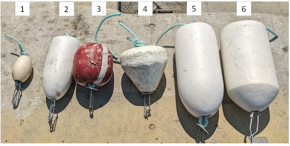
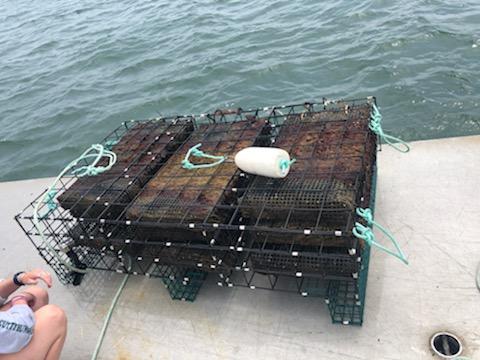
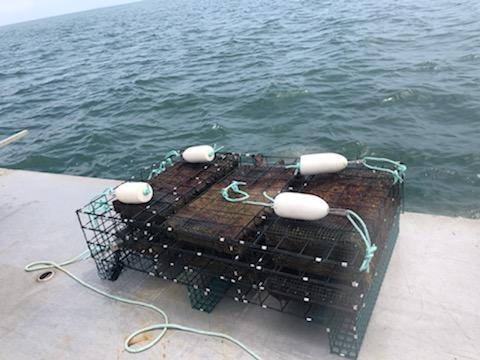
Just as a parachute uses air resistance to impart the proper orientation for the falling mass dropped from on high, buoys could provide a similar buoyancy effect for cages dropped in the water. Buoys come in a wide variety of shapes, sizes and buoyancies. For this study, we selected six different buoy types that were attached to the top panel of the oyster cage in two different orientations. The buoy characteristics are listed below (Table 1) and depicted in Figure 1, and the configurations of the buoy attachment to the cage is demonstrated in Figures 2a & b. To test each buoy type and configuration, the buoys were outfitted with a tuna clip to allow for rapid attachment of the buoy to rope loops installed on the cage. Functionally, the buoys would be permanently attached to the cage if this method were used commercially. Additionally, a GoPro camera was mounted on the outside of the cage with a range of view that projected down to allow for visualization of the substrate should the cage land in the proper orientation.
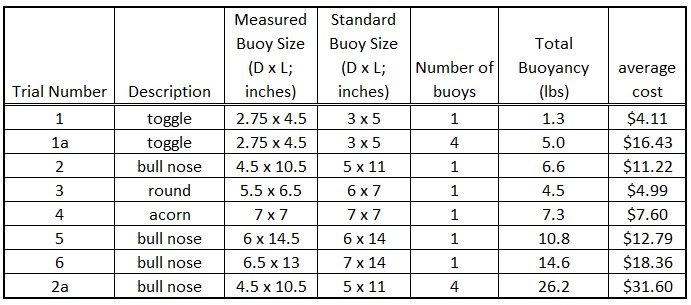
Each buoy type and configuration was evaluated via six releases of the buoyed cage from the surface and allowed to drop unimpeded to the bottom. The buoyed cages were released in either an upright orientation from the deck of the vessel (3 releases) or intentionally flipped upside down with the release to evaluate a worst case scenario (3 releases). Each drop was video recorded independently, and the video was observed to determine the orientation of the cage as it landed on the bottom (upright or not upright) as well as the elapsed time it took for the cage to drop from surface to bottom. Additionally, the average cost of each buoy type was determined from a general survey of buoy suppliers listed on the web.
After a series of drop tests on an empty cage to work out the protocols, the experimental cage was stocked with 9 oyster bags, each bag containing approximately 500 2” oysters, resulting in a filled cage estimated weight of approximately 250 lbs in air. The drop tests were conducted in approximately 18.5 feet of water depth at our farm site in Fairhaven, MA with the cage being slid off the deck of our aluminum work barge or intentionally flipped upside down when launched. A summary of the results of the series of drops under differing conditions of buoy size and placement are presented in Table 2.
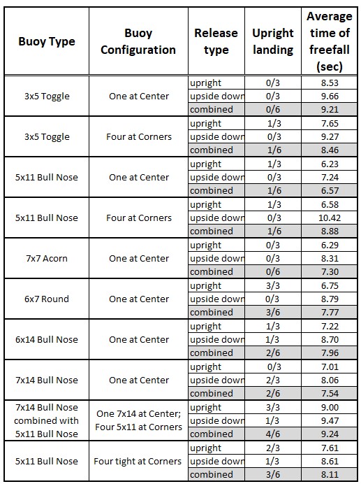
The ability of a buoy to induce enough buoyancy to force the cage into an upright condition while free falling through the water column was dependent on both the overall degree of buoyancy of the attached buoys coupled with the orientation of the cage release. As might be expected, the greater the amount of buoyancy attached to the cage resulted in more consistency in righting the free fall of the cage. For example, the best performance of a buoy system (4 correct landings out of 6 attempts) was the combination of a single 7x14 buoy in the cage top center with four 5x11 buoys at the corners. This buoy configuration provided a combined buoyancy of 30.8 lbs. or approximately 12% of the total cage weight. No buoy configuration tested was able to right the fall of the cage 100% of the time although the above referenced 5-buoy system was able to consistently ensure a proper landing when the cage was released from the surface in an upright orientation.
Cages that were released in an upside down configuration took longer to drop (average transit time for right-side up drops was 7.23+1.12 seconds and for upside-down drops was 8.91+0.95 seconds), required a higher amount of buoyancy to correct the orientation, and generally would not consistently flip to the proper orientation when released. Two factors may have been in play to prevent upside down releases from orienting properly. The first is that when handling the oyster cages on the deck, often the mass of oysters in each bag is concentrated at one end of the bag leading to an imbalance of mass in the cage. When the cage is released upside down with buoyancy, the momentum of the flip induced by the buoy cannot overcome the tendency of the cage to drop with the heavy side down as it rotates in the water. When the cage is released in an upright position from the surface, the buoy can stabilize the orientation of the cage enough such that when the cage hits bottom in the short amount of time in transit (overall average transit time in 18.5 feet of water was 7.23 seconds), although not square to the bottom, the tilt of the cage is not severe enough to prevent the cage from settling in an upright position.
The second factor in preventing upside-down cage releases from correcting their orientation while falling, specifically with the corner attachment points for the buoys, was the means of attaching the buoys to the cage. Loops of line were tied to each corner for buoy attachment and, combined with the tuna clip attachment devices, the overall distance from cage to buoy was over 1 foot (Figure 2b). Thus when the cage was released in an upside down orientation, the corner buoys would flip up along the side of the cage enough that the buoyancy being exerted tended to slow down the cage drop rather than impart a torsion to the drop to flip the cage into the upright position. After observing this in our cage drops, we shortened the attachment points for the 5x11 bull nose buoys at the corners for a final trial. As can be seen in Table 2, with the corner buoys held tighter to the cage top, the performance of the buoyancy improved the ability of the cage to correct itself in free fall (1/6 for the loose rope trial compared to 3/6 for the tight attachment.)
Method 2: Line release of cages on the bottom:
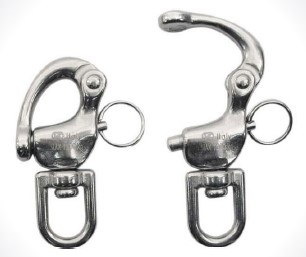
Lowering a cage from the surface via an attached line at the cage top would also impart the proper resistive force to ensure that the cage remain in an upright orientation as it is lowered to the bottom. However, having a large concentration of vertical lines at a farm site is routinely discouraged due to possible entanglement issues with critical marine fauna. Therefore, the lowering line cannot be permanently attached to the cage. Two means of temporarily attaching a line to a cage for lowering was evaluated. The first used a device called a “snap shackle” (Figure 3) that allows a tensioned line to be attached to the shackle which in turn is attached to the top of the cage. The shackle can be released from the tension by tripping a second line that opens the shackle and releases the cage to allow for retrieval of the lines and shackle. The second is a simple loop of line that is threaded through the center mesh of the top of the cage and its length is double the depth of the water where the cage is being deployed. The doubled line threaded through the top of the cage allows the farmer to lower the cage until it rests on the bottom. Then one side of the loop is released and pulled back through the mesh thus releasing it from the cage for retrieval.
Evaluation of the line release method for placing cages on the bottom consisted of observing the orientation of the cage on the bottom using the same protocol as was used for Method 1 above.
Observations of cage releases controlled by line attachments consistently resulted in the cages arriving at the seafloor in the proper upright orientation, 100% of the time. The drop of 9-bag bottom cages can easily be controlled in hand by a single person on deck at the surface. Both means to control line deployments worked well; however, the snap shackle apparatus had a tendency to trip unexpectedly as the trip line was free on deck and often would entangle in nearby apparatus thereby releasing the mechanism and allowing the cage to free fall from the time of release. The dual rope loop system was more reliable to ensure the cage was lowered to the bottom and did not appreciably add to the handling time of the cage release.
Objective 2: Develop a method to visualize the orientation and placement of cages on the bottom using commercially available “fish finder” technology.
Visualizing structure on the bottom of the bay, at depth, can be routinely demonstrated with a side-scan sonar apparatus, such as the Humminbird Solix 15. Initially, the Solix mount needed to be adapted in a way to to allow for easy transport and an ability to be operated from a variety of vessels in our work fleet. Once properly outfitted with transport and adaptable mounting hardware, the Solix was operated on our existing farm to understand the capabilities and limitations of the apparatus for visualizing structures on the bottom in 15 to 25 feet of water.
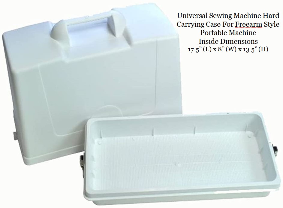
Our initial effort was directed at adapting the Solix for use. First, we need an appropriate protective case for transporting the head unit of the Solix. After searching, we discovered a plastic portable sewing machine case that was the correct size for housing the Solix head unit (Figures 4 & 5).
Additionally, the transducer, providing the sound source for the sonar detection, needed to be mounted on a portable device that allowed the transducer to be submerged from the boat while attached in a secure and stable manner. The transducer unit was bolted to one end of a 1-inch diameter and 6-foot length galvanized steel electrical conduit (Figure 6).
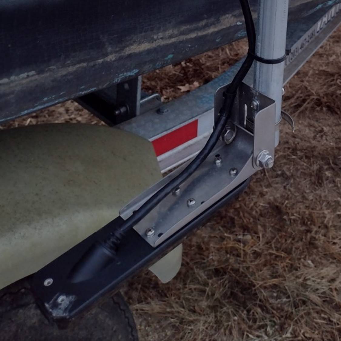
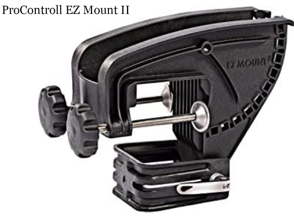
The conduit was then inserted in a fiberglass reinforced mount (ProControll EZ Mount II) available as a replacement mount for electric trolling motors (Figure 7).
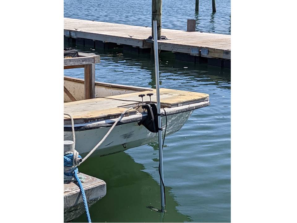
This mount allowed the transducer and pole to be attached to the gunnel of our work skiff during intervals when the Solix was in use (Figure 8).
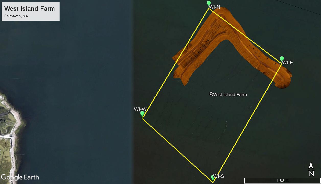
Once the Solix was installed, preliminary runs where recorded with the Solix to integrate the output of the Solix using software (SAR Hawk) designed to interpret and integrate the Solix output into a mosaic image of the bottom of the area surveyed. To evaluate the ability of the Solix to display cage structures on the bottom, transects of areas at our West Island Farm with known equipment on the bottom were surveyed using multiple vessels in the BSS fleet. One such area that was surveyed contained numerous empty 9-bay and 18-bay bottom cages. Figure 9 demonstrates a mosaic of two transects that were completed in that area, tracking the northeast and northwest boundaries of the West Island Farm.
Upon close inspection of the details of bottom structures within the transects, highlighted by the side imaging sonar configuration for the Solix 15, numerous important details could be observed. For example, Figure 10 identifies both 9- and 18-bay empty bottom cages on site. It was possible to differentiate the two cage types based on the height of the cage off the bottom and the subsequent length of the sonar shadow generated by each cage opposite from the direction of the incoming sonar signal (the blue dotted track down the center of the image.)
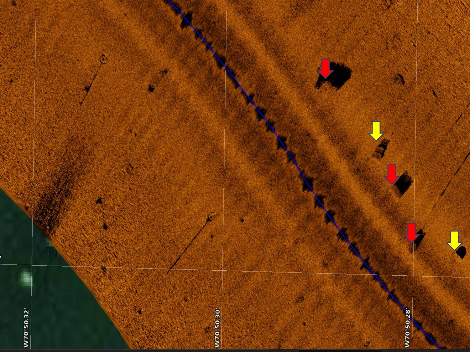
However, the resolution of the sidescan image was not detailed enough to distinguish the orientation of the cage on the bottom. Perhaps with more experience in fine-tuning the output of the side-scan, in terms of track width, brightness and contrast, details of cage orientation could be improved but it is not anticipated that the level of detail required to assess cage orientation will be achieved with the current equipment.
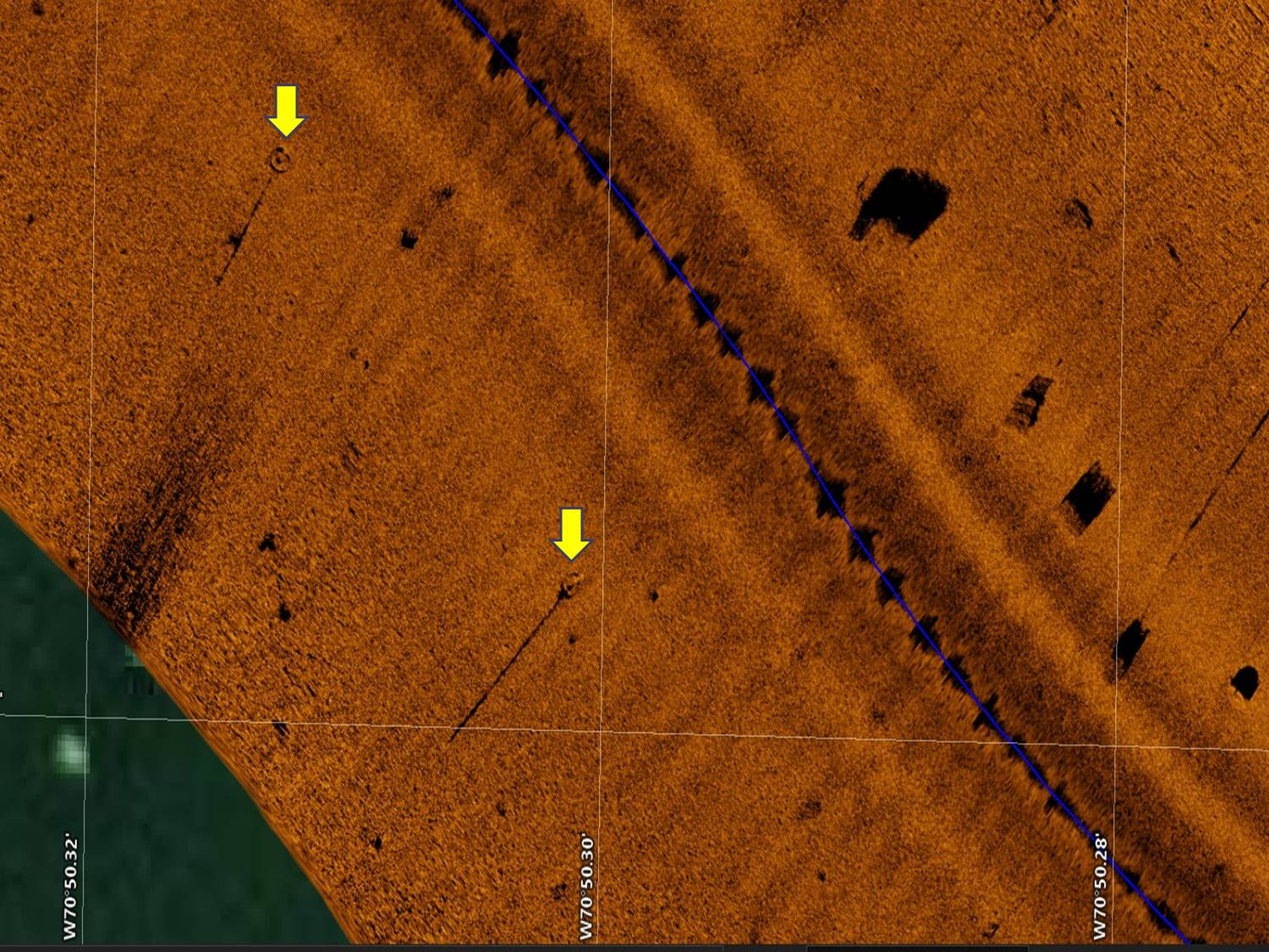
In addition to being able to visualize empty cages on the bottom, the sidescan image generated by the Solix also located two train wheels that are used as anchors for the longlines associated with our floating cages at the site (Figure 11).
Another application of the Solix 15, in alignment with the efforts of the Delaware group in monitoring for ghost traps, is to locate and visualize debris fields on the farm site, left from earlier mismanagement of the site. Again, debris on the bottom cannot be observed from the water surface and therefore having a means to visualize these structures extends the farm manager's capacity to keep the site free of hazardous debris on the bottom. As an example, while generating the transects noted in Figure 9, as we turned the north corner of the farm site, we encountered an array of twenty floating cages that had been intentionally sunk in a previous winter to avoid ice damage to the cages. However, the previous manager must have forgotten the location of this line of twenty cages and they were abandoned on site. We were able to easily locate this forgotten line through the images from the Solix 15 (Figure 12)
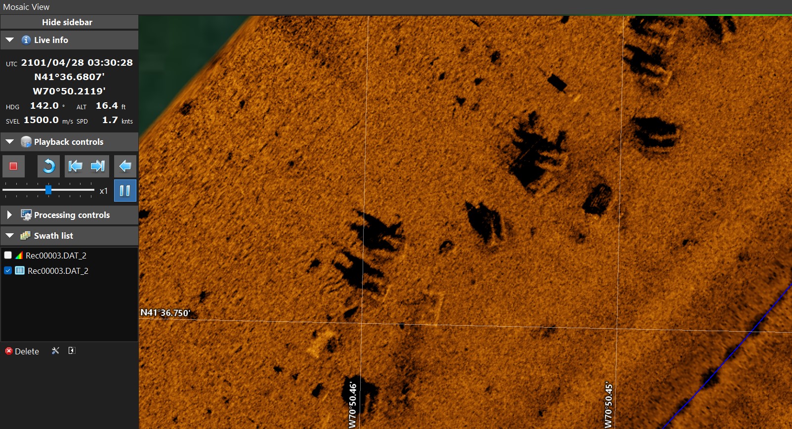
Furthermore, within the image, we were able to discern that these cages were sitting on the substrate in an upside down orientation (float structures were oriented up rather than functioning as legs and oriented down), suggesting that the cages had been sunk improperly and that the oyster seed held in the cages was probably lost due to silting of the bags in direct contact with the substrate.
A quick cost analysis of the SOLIX system in 2022 totals up to an investment of approximately $4,500 to set yourself up with a very sophisticated yet relatively easy to use down and side imaging sonar system for monitoring the status of equipment on the bottom at your deep water farm.
Objective 1: Develop a means to ensure that cages released from the surface will land on the bottom in an upright orientation.
Attaching buoys to cages as parachutes to control the ascent of the cage to the bottom worked with limited success. Even with 30 lbs. of buoyancy attached to the cage, there was only a 67% assurance that the cage would land in the proper orientation. The success rate increased to 100% if the crew deploying the cage carefully released the cage from the surface with an upright orientation to the release. However, employing the 5-buoy configuration to each bottom cage increased the overall cost of the apparatus from $244 for a 9-bag cage kit by an additional $49 for the buoys. That is a 20% increase to the cost of a cage. Given the additional cost and uncertainty of the success rate of the apparatus, BSS has decided to not employ this strategy for cage deployments.
A rope controlled cage assent proved to be 100% reliable and relatively simple and inexpensive to implement. While the snap shackle was problematic at times, the dual loop rope release worked without a flaw and did not result in additional time lost while deploying the cages from the barge. Therefore, this method has become the one of choice for deploying bottom cages in deeper waters at the Blue Stream Shellfish farms.
Objective 2: Develop a method to visualize the orientation and placement of cages on the bottom using commercially available “fish finder” technology.
The utilization of a Humminbird Solix 15 to visualize structures on the bottom in a deeper water farm was a complete success. The Solix 15 is relatively easy to have up and running in a transportable mode. After a short session on the water adjusting the operating parameters, utilizing a wide array of "how to" videos available on the web for set-up and fine tuning of the Solix series of fish finders, BSS was able to put the unit to immediate use in mapping out the bottom of both West Island and Seal Rock Farms, using the instrument coupled with the SAR Hawk software. While we were not able to fine tune the resolution of the instrument to allow us to detect the orientation of a 9-bay cage on the bottom, right side up versus upside down, we easily were able to identify cages in place and could tag both non-buoyed cages and debris on the floor of the farm for future retrieval. This unit will be instrumental in our efforts to develop a ropeless cage technology at our Seal Rock Farm, where vertical lines in the water are discouraged due to entanglement issues.
Education & outreach activities and participation summary
Participation summary:
Visualizing bottom cages_NACE 2022
NACE 2022 abstract_How do you find those oyster cages on your deep water farm
Actual Powerpoint presentation given at NACE in April 2022, with approximately 25 individuals attending the presentation.
projects.sare.org/…/NACE-2022-abstract_How-do-you-find-those-oyster-cages-on-your-deep-water-farm.pdf
Abstract submitted for presentation at the Northeast Aquaculture Conference and Exposition held in Portland, ME. Originally scheduled for 12-14 January 2022, the conference was postponed to 27-29 April 2022 due to COVID precautions.
Technical Bulletin - Cage Drop Technology
The technical bulletin developed in collaboration with Josh Reitsma (Project Technical Advisor) and published by Woods Hole Sea Grant/Cape Cod Cooperative Extension. Hard copies are available.
Additionally, a video of the application of sidescan sonar technology for deeper water oyster farms was produced and uploaded to a Cape Cod Cooperative Extension YouTube site. https://youtu.be/8msFO6DUgUk
Learning Outcomes
This project developed an awareness in farmers that side-scan sonar is an option for monitoring the cage placement on their farms.
Project Outcomes
Outcomes from activities in 2021
Outcomes for Objective 1:
After testing a number of tools to ensure the proper landing orientation of bottom oyster cages when released from the surface into deeper waters (~20 feet), only one was deemed as satisfactory to guarantee the cage landed in an upright stance. By using a tether line to lower the cage to the bottom and releasing the line for retrieval once the cage had settled, we were assured that the cage was properly set 100% of the time. The use of buoys to hold falling cages upright and/or a snap shackle to hold and release the cage was not 100% effective and resulted in a risk of cages being placed on their side or upside down when released.
Outcome for Objective 2:
The use of a commercially available fish finder (Humminbird SOLIX 15) that incorporated down- and side-looking sonar coupled with dedicated software (SAR Hawk) to integrate the sonar output proved to be an effective tool for "observing" oyster cages as they sat on the bottom in deeper waters (~20 feet). While the resolution was not adequate to monitor the exact orientation of the cage on the bottom, further manipulation of the operating parameters of the sonar may lead to improved capabilities of the unit to observe cage orientation. Regardless, the system was very effective in locating cages and other structures on the bottom of the farm, including cast off debris and/or lost gear. The use of sonar will become an integral component to managing our farm in the future.
Overall, I was very satisfied with the results of this study. Our work provided two tools that immediately were integrated into our farm operations and will help us manage our farm more effectively.
However, there is room for more work to be completed to improve the results of Objective 2. We believe that adjustments to the side-scan sonar unit we used can be further manipulated to provide better resolution of the structures located on the bottom of our oyster farm. We will be experimenting with tweaking the unit and software as we continue to become familiar with the capabilities of the system. We immediately plan to generate a mosaic of the bottom of our entire farm to characterize all bottom structures in place on the farm. This information will be augmented by a substrate survey to try to correlate the substrate type with the sidescan signal generated by the unit. Ultimately, we will be able to monitor how the bottom characteristics change over time as the farm operations and stocking density become more intense as we approach our goal of increasing the production capacity of the farm. We also plan to further experiment with placing structures on our cages that may enhance the signal from the cage to allow for a more detailed interpretation of the side-scan representation of the cage orientation on the bottom as we believe this to be a critical aspect of farm operations, based on previous performance on the farm.